


EPSON Stylus Photo 750 Revision A
Disassembly and Assembly Disassembly 55
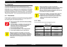
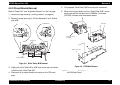
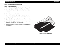
4.2.2 Circuit Boards Removal
Refer to “Check Point” and “Adjustment Required” on the next page.
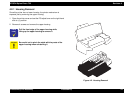
1. Remove the upper housing. (“Housing Removal” on page -54)
2. Remove 5 screws securing the “Printer Mechanism” to the “Shield
plate, M/B”.
Figure 4-3. Shield Plate, M/B Removal
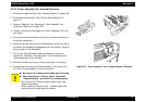
3. Slightly pull out the “Shield Plate, M/B” and remove the cable holder
installed on the “Shield Plate, M/B”.
4. Disconnect all the cables from the connectors on the C259 main
board.
5. Fully separate “Shield Plate, M/B” from the printer mechanism.
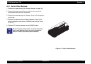
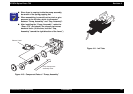
6. When removing each board unit from “Shield Plate, M/B”, remove
each screw securing the each board (C259Main: 10 screws,
C257PSB: 4 screws), and remove each board.
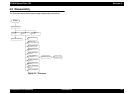
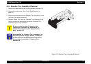
Figure 4-4. C259 Main Removal
NOTE: When removing C257PSB, disconnect cables connected to
the C259 main board.
[C a b le H o ld e rs ]
SHIELD PLATE, M/B
M A IN B o a rd
(C259 M AIN)
Power Supply Board
(C257 PSB)
SHIELD PLATE, M/B