


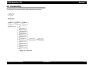

EPSON Stylus Photo 750 Revision A
Disassembly and Assembly Disassembly 61
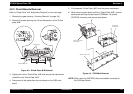
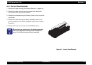
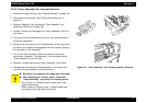
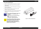
4.2.5.2 Pump, Assembly/Cap, Assembly Removal
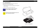
1. Remove the upper housing. (See “Housing Removal” on page -54)
2. Remove the control panel. (See “Control Panel Removal” on
page -57)
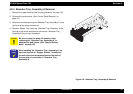
3. Remove “Absorber Tray, Assembly;A” (See “Absorber Tray,
Assembly;A Removal” on page -58)
4. Loosen 2 screws and disengage the “Frame, Assembly, Exit” and
side frame.
5. Sand up the printer mechanism so that you can see the bottom of
the printer mechanism.
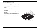
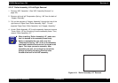
6. Remove one hook securing the “Cap Assembly” at the right side of
the frame, and release the engagement with the frame by lifting up
the right side of “Cap Assembly”.
7. Pull out the “Cap Assembly” toward the bottom of the printer
mechanism. (However, “Cap Assembly” is still connected to the
“Pump Assembly” by the ink tube.)
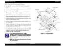
8. Remove 2 screws securing the “Pump, Assembly” to the frame.
9. Release one hook securing “Pump Assembly” to the frame, and
move the “Pump Assembly” to left and remove it.
Figure 4-9. “Cap, Assembly” and “Pump Assembly” Removal
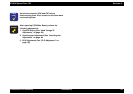
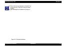
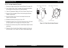
CAUTION
„
Be careful not to damage the rubber part of the cap.
„
When handling the “Cleaner, Head” installed at
“Pump Assembly”, be careful for following points.
• Do not touch the “Cleaner, Head” by bare hand. Use
globe and tweezers.
• When installing “Cleaner, Head”, its black rubber side
should face to the right side of the frame.