


EPSON Stylus Photo 750 Revision A
Troubleshooting Overview 39
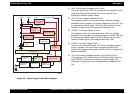
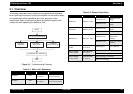
3.1 Overview
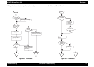
This section describes how to identify and troubleshoot the problems
when repairing the printer by dividing the troubles into two levels; repair
and replacement of the assemblies and units, and repair of the
components. Refer to the flowchart below and perform repairing the
component after separating the defective units.
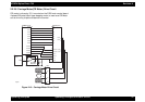
Figure 3-1.
Troubleshooting Flowchart
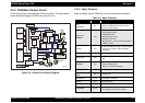
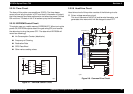
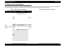
Table 3-1. Motor, Coil Resistance
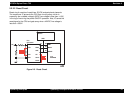
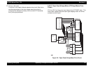
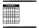
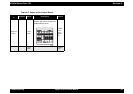
Table 3-2. Sensor Check Point
Motor Location Check Point Resistance
CR Motor CN7
Pin 1 and 3
Pin 2 and 4
7.8 Ohms
±
10% (at
25
°
C/one phase)
PF Motor CN8
Pin 1 and 3
Pin 2 and 4
8.8 Ohms
±
10%
(at 25
°
C/one phase)
START
END
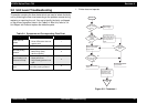
Unit Level Troubleshooting
Unit Repair
(P S B /P S E )
Unit Repair
(M ain board)
Disassem ble and Adjustm ent
Unit Repair
(P rin te r M e ch a n ism )
Sensor Name Check Point Signal Level Switch Mode
HP Sensor CN4/Pin 1 and 2
Less than 0.7V
Open (Out of HP
range)
More than 2.4V
Close (Within HP
range)
PE Sensor CN5/Pin 1 and 2
Less than 0.7V
Open (Paper
exists)
More than 2.4V Close (No paper)
ASF Sensor CN6/ Pin 1 and 2
Less than 0.7V
Open (Paper Feed
Roller home
position)
More than 2.4V
Close (Out of home
position)
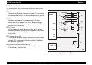
Thermistor
(THM)
Head side CN9/
Pin 3 and 4
Analog signal 10 K (at 24
°
C)
Black cartridge
sensor (COB)
Head side CN9/
Pin 1 and 4
Open (Cartridge is installed)
Close (No Cartridge)
Color cartridge
sensor (COC)
Head side CN9/
Pin 2 and 4
Open (Cartridge is installed)
Close (No Cartridge)