


EPSON Stylus Photo 750 Revision A
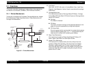
Operating Principles Operating Principles of Electric Circuit 35
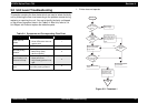
2.2.2.4 Timer Circuit
The timer of this printer uses reset/timer IC(IC8). The timer keeps
record of how long the printer is OFF and uses it information to judge it
the initial cleaning should be performed or not when the power it turned
ON next time. The data in the IC is backed up by the lithium battery.
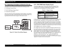
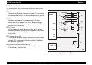
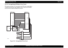
2.2.2.5 EEPROM Control Circuit
This printer uses non-volatile memory EEPROM(IC7). When turning the
power ON, EEPROM outputs data to the gate array(IC2) and records
the data when turning the power OFF. The data which EEPROM will
record are followings;
„ Ink Consumption Counter (black/color)
„ Frequency of Cleaning
„ Destination Data
„ CPSI Pass Word
„ Other various setting values
Figure 2-7. EEPROM Control Circuit
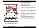
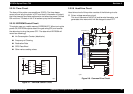
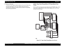
2.2.2.6 Head Drive Circuit
Head drive circuit of this printer consists of the following circuits.
† Driven voltage wave form circuit
This circuit consists of HIC(IC14) and terminal transistor, and
generates drive wave which will be charged to each PZT.
Figure 2-8. Common Drive Circuit
+5V
8
6
5
AT93C46
(IC7)
Vcc
GND
ORG
E05B58**
(IC2)
206
205
204
203
1
2
3
4
CS
SK
DI
DO
EECS
EECK
EECO
EECI
op07
CXA20996(IC14)
VCC45
Vcc45_2
NPNB
FB
PNPB
VOUTGND
F1
E05B58**(IC2)
VHCTL
22
20
CCO
LAT
CLK
BCO
THM
1
2
5
14
11
3
190
SWC0
184
HLAT
IECLK
AN0
105
A0
A1
A2
A3
CLK1
CLK2
/FLOOR
/RST
DATA
DCLK
/E
HWA0
HWA1
HWA2
HWA3
HWCLK1
HWCLK2
/HWFLR
/HWRST
HWSDATA
HWSCLK
/HWSLAT
SI1
12
174
HNCHG
+42
23
18
16
22
21
20
19
26
25
24
23
GND2
GND2
GND2
GND2
COM
COM
COM
COM
VHV
27
VCC5
+5
24
14
SWC1
189
173
NCHG
16
HCLK
175
176
HSI1
SI2
HSI2
177
10
SI3
HSI3
178
8
SI4
9
179
HSI4
SI5
HSI5
180
7
SI6
HSI6
181
TMP95C061(IC1)
GND
GND
GND
GND
GND
+5
GND
18
17
15
13
6
4
CN9
op08