


EPSON Stylus Photo 750 Revision A
Disassembly and Assembly Disassembly 75
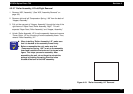
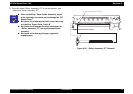
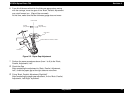
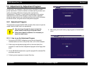
Figure 4-29. Sensor, I/C Removal
5. Separate “Sensor, IC” from the harness by releasing its connection.
CHECK
POINT
„
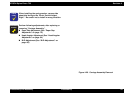
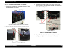
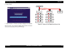
Be careful of the direction of sensor, when
installing it. Switch part should face to the front
side.
„
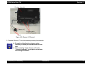
When installing “Holder, Sensor, I/C” to the
“Carriage, Assembly”, do not pinch the harness
with carriage and holder.
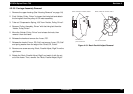
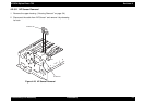
Carriage Assembly
Engaging parts
at the carriage side
Hooks
Sensor, I/C