


EPSON Stylus Photo 750 Revision A
Operating Principles Overview 28
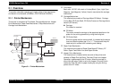
2.1 Overview
This section describes operating principles of the printer mechanism
and electric circuit boards (C259Main, C257PSB and C209PNL).
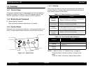
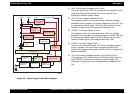
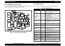
2.1.1 Printer Mechanism
This printer is composed of Print Head, Carriage Mechanism, Hopper
Drive Mechanism, Paper Feed Mechanism, Pump Mechanism and
Carriage Lock Mechanism.
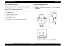
Figure 2-1. Printer Mechanism
† Print Head
Each color 120 DPI, 48 nozzle x 6 colors(Black, Cyan, Light Cyan,
Magenta, Light Magenta, Yellow). Head is mounted at the carriage
mechanism.
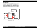
† Carriage Mechanism
This mechanism consists of Carriage Motor(CR Motor), Carriage,
Timing Belt, CR Guide Shaft, CR Guide Frame and Carriage Home
Sensor (HP Sensor).
„ Carriage
Print Head is mounted.
„ CR Motor
This motor moves the carriage to the appointed position on the
platen for the printing operation by using the timing belt.
„ CR Guide Shaft
Since this guide shaft is ecentric shaft, it is rotated by the adjust
lever and sets the platen gap “0“ or “+”. This prevents the print
head and print surface from contacting and rubbing.
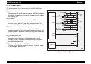
† Paper Feed Mechanism
This mechanism consists of Paper Feed Motor(PF Motor), PF
Roller, Paper Feed Roller Line and Paper Guides.
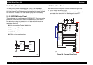
† Hopper Drive Mechanism
This mechanism is installed at the rear side of the printer and
consists of Paper Pick Up Roller, One-way Clutch and Hopper.
Operation is performed by the PF motor, when the carriage is
around the left edge. Paper is set to the hopper. One-way clutch
rotates the Pick Up roller for paper loading by using the driving
power of the PF motor.
CR Motor
P F M o to r
Pump
Tim ing Belt
Carriage M echanism
(Print Head)
Paper Load
Trigger
Carriage Lock
M echanism
Pump Mechanism
Paper Feed
M echanism
Hopper Drive
M echanism
op1