


EPSON Stylus Photo 750 Revision A
Operating Principles Operating Principles of Electric Circuit 30
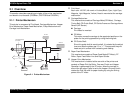
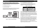
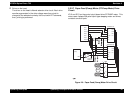
2.2 Operating Principles of Electric Circuit
The electric circuit of this printer consists of the following circuits.
† C259 Main Control Circuit
† C257 PSB Power Supply Circuit
† C209 PNL Panel Board
Also, the head drive circuit is mounted on the print head. In this section,
the operating principles of C257PSB board and C259 Main board. The
figure below shows the block diagram of the electric circuit.
Figure 2-2. Electric Circuit Block Diagram
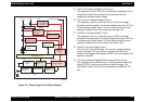
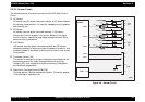
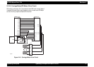
2.2.1 C257 PSB Power Supply Circuit
The power supply circuit in the printer uses RCC(Ringing Choke
Converter) circuit method, and generates and outputs 2 types of
voltages which are necessary for the printer operation.
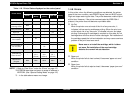
Table 2-1. Output Voltage
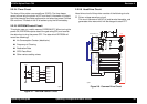
In this printer, even if the power switch is turned off in the middle of the
printing operation, application of the secondary switch enables the
printer to supply the voltage to the power/logic lines at the main board
side for at least 30 seconds. Therefore, even if the switch is turned off in
the middle of the printing operation, the power will be turned off after the
capping operation is completed. This prevents the print head from being
left uncapped and dry, and also ink leaking.
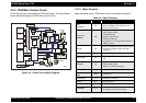
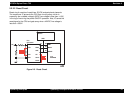
AC voltage input from the AC inlet passes through the Filter Circuit at
first, which removes the high frequency component, then, goes to Full
Wave Rectifier Circuit and Smoothing Circuit and is converted to DC
power supply. Then, this direct voltage is led to the Switching Circuit
and is performed with switching operation by FET Q1. By the switching
operation in the primary side circuit, +42 VDC is generated and
stabilized in the secondary side. The +42VDC generated at the
secondary side is converted to more stabilized +5VDC by the chopping
regulator IC located at the secondary side.
Voltage Usage
+42VDC
•Motors
• Print Head common voltage
+5VDC
• C259Main Control Circuit Logic
• C209 PNL Panel Board
•Sensors