


EPSON Stylus Photo 750 Revision A
Operating Principles Operating Principles of Electric Circuit 36
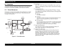
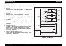
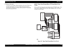
† Driver on the head
The driver on the head is Nozzle-selector drive circuit. Each drive
waveform generated in the drive voltage wave form circuit is
charged to the selected nozzle by this circuit with PZT elements,
then, printing is performed.
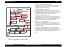
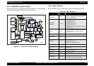
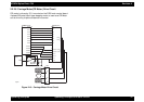
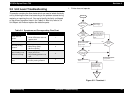
2.2.2.7 Paper Feed (Pump) Motor (PF/Pump Motor) Drive
Circuit
IC12 and IC13 on the control circuit board drive PF/PUMP motor. This
motor uses 4-phase 200-pole Hybrid type stepping motor and drives
constant current bi-pola.
Figure 2-9. Paper Feed (Pump) Motor Drive Circuit
+5
M6252(IC16)
-
+
7
6
5
C90A05
(IC1)
112
DA1
D0
D1
D2
PHASE
REF
PFD
A3956(IC13)
OUTA
OUTB
VBB
VCC
Current
Detection
D0
D1
D2
PHASE
REF
PFD
A3956(IC12)
OUTA
OUTB
VBB
VCC
4
5
6
7
E05B58**(IC2)
PFIB0
PFIB1
PFIB2
PFPHAB
PFIA0
PFIA1
PFIA2
PFPHAA
8
9
10
11
14
9
8
7
2
1
14
9
8
7
2
1
10
15
Rotor
A
/A
B
/B
1
3
2
4
CN8
10
15