


EPSON Stylus Photo 750 Revision A
Operating Principles Operating Principles of Electric Circuit 32
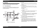
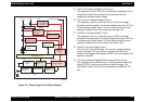
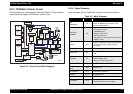
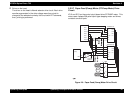
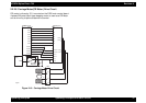
2.2.2 C259 Main Control Circuit
Printer mechanism is controlled by C259 main board. The figure below
shows the block diagram of C259 main control circuit.
Figure 2-4. Control Circuit Block Diagram
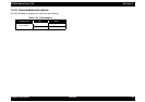
2.2.2.1 Major Elements
Major elements used in C259 main control circuit board are below.
Table 2-2. Major Elements
op04
Address
Data
Reset IC
(IC9)
CR1
Timer
Counter
(IC8)
Batt1
EEPROM
(IC7)
CN1 Parallel
Q2&Q3
Head
CN9 HD FFC
PF Motor
CR Motor
CN7
C209 PNL
CN11
CN6
ASF Sensor
CN4
HP Sensor
CN5
PE Sensor
Transceiver
(IC9)
CN2 Mac. Serial
Motor
Driver
(IC13)
Common
Driver
(IC14)
CN8
Motor
Driver
(IC12)
Buffer
(IC9)
CN3 USB
P-ROM
(IC3)
D-RAM
(IC4)
M-ROM
(IC6)
Motor
Driver
(IC11)
C90A05
(IC1)
E05B588
(IC2)
Cartridge Sensor
IC Location Function
CPU
C90A05CA
IC1
16bit CPU mounted on the control circuit board
is driven by 24MHz clock frequency, and
controls the whole printer.
Gate Array
E05B58**
IC2
• Motor control
• Head voltage control
• EEPROM control
• Monitoring the sensor
• Monitoring Timer IC
• Mac,Serial I/F, running direction parallel I/F,
USB I/F control
PROM IC3
Volume 4/8/16MB, Bus width 16 bit EEPROM
• Program or program +CG(k character
generator)
RAM IC4 Bus width 16 bit, 4Mbit DRAM
Mask ROM IC6
64Mbit Mask ROM
•CG
AT93C46 IC7
1kBit EEPROM
• Default Setting Value
• Back-up of various parameter
RTC-9810SA IC8 Reset/Timer IC
74VHC161284
MEA
IC9 Transceiver IC
SN75LBC777 IC10 RS-422/423 Transceiver
LB1847 IC11 CR motor drive iC
A3956ALB IC12,13 PF/PUMP Motor drive IC
CXA2099S IC14
Head drive control HIC
• Generating head common voltage