


EPSON Stylus Photo 750 Revision A
Operating Principles Operating Principles of Electric Circuit 33
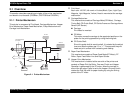
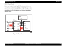
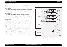
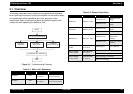
2.2.2.2 Reset Circuit
Reset circuit consists of reset/timer IC(IC8) and peripheral elements.
The reset/timer IC prevents the CPU from running away, which is
caused by the unstable voltage(+5VDC line voltage is less than +4.3V)
in the logic line during the power ON/OFF operation. Also, IC sends the
reset signal to the CPU and gate array when +42VDC line voltage is
less than +35.5V.
Figure 2-5. Reset Circuit
/NMI
MRES
/RESET
IC 1
C90A05
/RES
B1
10
3
2
29
24
25
+42 VIN
VDD
VBK
GND
/VDT
FRST
/RST
CE
SCLK
DATA
IC 8
RTC-9810
IC 2
E05B588