90 EPSON S1C63558 TECHNICAL MANUAL
CHAPTER 4: PERIPHERAL CIRCUITS AND OPERATION (Serial Interface)
Timing chart
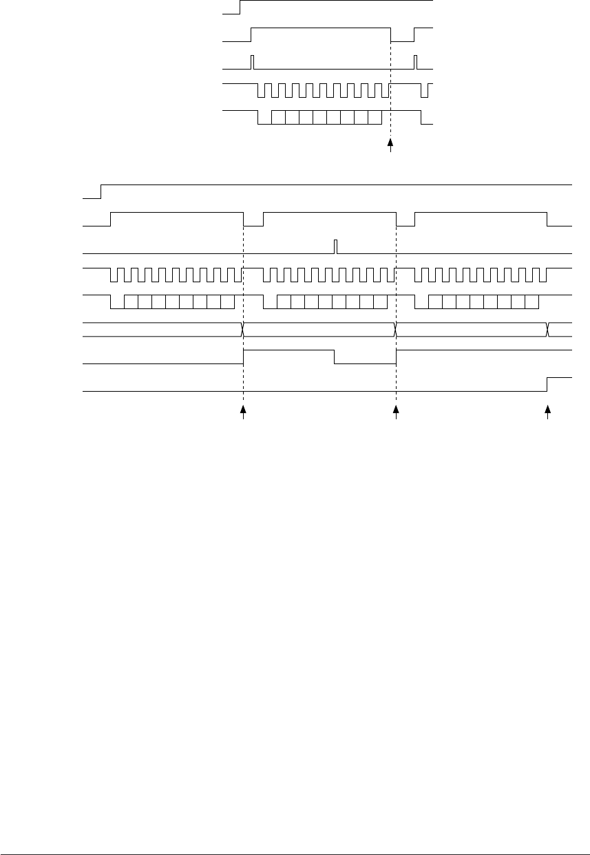
Figure 4.11.7.4 show the asynchronous transfer timing chart.
TXEN
TXTRG(RD)
TXTRG(WR)
SOUT
Interrupt
(In 8-bit mode/Non parity)
D0 D1 D2 D3 D4 D5 D6 D7
Sumpling
clock
(a) Transmit timing
RXEN
RXTRG(RD)
RXTRG(WR)
SIN
TRXD
OER control signal
OER
Interrupt
(In 8-bit mode/Non parity)
D0 D1 D2 D3 D4 D5 D6 D7 D0 D1 D6 D7 D0 D1 D2 D3 D4 D5 D6 D7D2 D3 D4 D5
1st data 2st data
Sumpling
clock
(b) Receive timing
Fig. 4.11.7.4 Timing chart (asynchronous transfer)
4.11.8 Interrupt function
This serial interface includes a function that generates the below indicated three types of interrupts.
• Transmitting complete interrupt
• Receiving complete interrupt
• Error interrupt
The interrupt factor flag ISxx and the interrupt mask register EISxx for the respective interrupt factors are
provided and then the interrupt can be disabled/enabled by the software.
Figure 4.11.8.1 shows the configuration of the serial interface interrupt circuit.


