


S1C63558 TECHNICAL MANUAL EPSON 113
CHAPTER 4: PERIPHERAL CIRCUITS AND OPERATION (Telephone Function)
4.14.2 Mask option
Output specifications for the DP terminal is selected from between complementary output and Nch open
drain output by mask option.
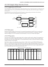
Since the R10 to R13 terminals are used for XTMUTE, XRMUTE, HDO and HFO outputs, the output
specifications of the output ports R10–R13 apply to their output specifications. Either complementary
output or Nch open drain output can be selected for each terminal by the output port mask option.
However, even when Nch open drain output is selected, voltage exceeding source voltage must not be
applied to the output terminals.
4.14.3 Operation of telephone function
To realize the operation of the telephone function, dialing procedure is the most important concept. This
procedure contains three steps: (1) setting, (2) executing and (3) interrupt.
(1) Setting
Every function has its control registers. It is necessary to set the appropriate control registers before
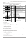
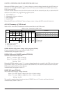
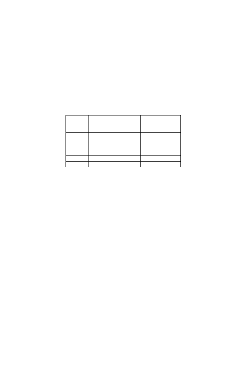
execution. Table 4.14.3.1 lists the relations of functions and control registers.
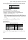
Table 4.14.3.1 Control registers and default setting
Function
DTMF
DP
PAUSE
FLASH
Control register
TPS (FF10H•D3)
SINC, SINR (FF16H)
TPS (FF10H•D3)
MB (FF10H•D1)
DRS (FF10H•D0)
IDP3–IDP0 (FF15H)
PTS3–PTS0 (FF11H)
FTS3–FTS0 (FF12H)
Initial setting
Tone mode
Dual tone
Tone mode
40 : 60
10 pps
750 ms
4 sec
563 ms
See Section 4.14.10, "I/O memory of telephone function", for details of each control register.
Operating mode
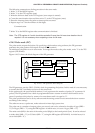
This dialer has built-in a DTMF generator for generating tones and a DP generator for generating dial
pulses. Two basic operating modes are provided: tone mode and pulse mode. The mode can be
switched by software (TPS register). This setting must be performed prior to the dial processing. At
initial reset, tone mode is set.
The following operating condition should be set according to the operating mode:
Tone mode: • Selecting single tone or dual tone output
Pulse mode: • Setting a make ratio (40:60 or 33.3:66.6)
• Setting a pulse rate (10 pps or 20 pps)
•
Setting an inter digit pause time (94 msec to 1,406 msec; selected from among 15 types)
Details will be discussed later.
The tone mode uses the OSC3 (3.58 MHz) clock, so the OSC3 oscillation must be turned ON (OSCC =
"1") prior to dialing. However, it is not necessary to switch the CPU system clock to OSC3.
When executing the pause or flash function, the period of time should be set.
Pause time: 1 to 15 sec (1-sec units; selected from among 15 types)
Flash time: 94 msec to 1,406 msec (selected from among 15 types)
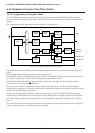
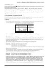
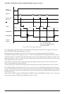
Furthermore, to use the R10 to R13 terminals for the XTMUTE, XRMUTE, HDO and HFO outputs, the
output port functions must be switched to the dialer using the CTMO, CRMO, CHDO and CHFO
registers (by writing "1"). This switching should be followed the procedure shown in Figure 4.14.3.1
(sample XTMUTE and XRMUTE outputs). The high impedance control registers (R10HIZ–R13HIZ)
must be fixed at "0" and the data registers (R10–R13) at "1" before writing "1" to the CTMO, CRMO,
CHDO and CHFO registers. Also the mute control registers (CTMUT, CRMUT) should be set to "1".