


S1C63558 TECHNICAL MANUAL EPSON 39
CHAPTER 4: PERIPHERAL CIRCUITS AND OPERATION (Output Ports)
PTOUT: TOUT output control register (FFC1H•D2)
Controls the TOUT output.
When "1" is written: TOUT output ON
When "0" is written: TOUT output OFF
Reading: Valid
By writing "1" to the PTOUT register when the R02 register has been set to "1" and the R02HIZ register
has been set to "0", the TOUT signal is output from the R02 terminal. When "0" is written, the R02 termi-
nal goes high (V
DD).
When using the R02 output port for general-purpose output, fix this register at "0".
At initial reset, this register is set to "0".
FOUTE: FOUT output control register (FF06H•D3)
Controls the FOUT output.
When "1" is written: FOUT output ON
When "0" is written: FOUT output OFF
Reading: Valid
By writing "1" to the FOUTE register when the R03 register has been set to "1" and the R03HIZ register
has been set to "0", an FOUT signal is output from the R03 terminal. When "0" is written, the R03 terminal
goes high (V
DD).
When using the R03 output port for general-purpose output, fix this register at "0".
At initial reset, this register is set to "0".
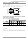
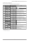
FOFQ0, FOFQ1: FOUT frequency selection register (FF06H•D0, D1)
Selects a frequency of the FOUT signal.
Table 4.5.5.2 FOUT clock frequency
FOFQ1
1
1
0
0
FOFQ0
1
0
1
0
Clock frequency
f
OSC3
f
OSC1
f
OSC1
× 1/8
f
OSC1
× 1/64
At initial reset, this register is set to "0".
CTMO: R10 output selection register (FF13H•D0)
Selects the R10 terminal function.
When "1" is written: XTMUTE output
When "0" is written: General-purpose DC output
Reading: Valid
When using the R10 terminal for the XTMUTE output, write "1" to this register. Furthermore, fix the R10
register at "1" and the R10HIZ register at "0". Refer to Section 4.14, "Telephone Function", for controlling
the XTMUTE output.
When using the R10 output port for a general-purpose output, fix this register at "0".
At initial reset, this register is set to "0".