


S1C63558 TECHNICAL MANUAL EPSON 119
CHAPTER 4: PERIPHERAL CIRCUITS AND OPERATION (Telephone Function)
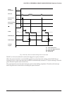
The following summarizes a dialing procedure in the tone mode:
1. Write "1" to the HSON register.
2. Write "1" to the CTO register. (note)
3. Write the dial tone data to the TCD register. (tone output is started)
4. Count the tone duration time and then write "0" to the CTO register. (note)
5. Reset the interrupt factor flag after an interrupt has occurred.
6. Repeat steps 2 to 5 for the number of dial digits.
:
Communication
:
7. Write "0" to the HSON register after communication is finished.
Note: The CTO register in 2 and 4 should be controlled if more than 94 msec tone duration time is
required. It is not necessary when outputting a tone for 94 msec.
4.14.5 Pulse mode (DP)
The pulse mode outputs dial pulses. By specifying a dial number using software, the DP generator
generates the pulse pattern and outputs it from the DP terminal.
At initial reset, the dialer is set in tone mode. To change the mode to the pulse mode, write "1" to the TPS
register (FF10H•D3).
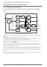
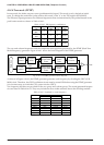
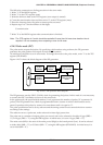
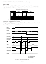
Figure 4.14.5.1 shows the block diagram of the DP generator.
Data bus
32 kHz
Oscillator
Frequency
Divider
Control
Registers
Timing
Control
Programmable
Down
Counter
DP
Data bus
32 kHz
oscillator
Frequency
divider
Control
registers
Timing control
circuit
Programmable
down counter
DP
Fig. 4.14.5.1 DP generator block diagram
The DP generator uses the OSC1 (32 kHz) clock for generating dial pulses. In this mode it is not necessary
to control the OSC3 oscillation circuit as in the tone mode.
In the pulse mode, the specified dial number (1 to 9) represents the number of pulses ("0" represents 10
pulses). The DP generator has a built-in programmable down counter in which a dial number can be
preset. It produces dial pulses by means of a count down until it is equal to "0".
The pulse specification can be set by software and the timing control circuit controls the down counter
according to the settings.
The software can set a pulse rate, make ratio and an inter-digit pause time.
The pulse rate is a number of output pulses per second, and can be selected to be either 10 pps (DRS =
"0") or 20 pps (DRS = "1") using the DRS register. At initial reset, it is set to 10 pps (DRS = "0").
The make ratio (M:B) is the ratio of the make period (High) to the break period (Low). It can be selected
to either 40:60 (MB = "0") or 33.3:66.6 (MB = "1") using the MB register (FF10H•D1). At initial reset, it is
set to 40:60 (MB = "0").