


S1C63558 TECHNICAL MANUAL EPSON 69
CHAPTER 4: PERIPHERAL CIRCUITS AND OPERATION (Programmable Timer)
4.10.5 Interrupt function
The programmable timer can generate an interrupt due to an underflow of the timer 0 and timer 1. See
Figure 4.10.2.1 for the interrupt timing.
An underflow of timer 0 and timer 1 sets the corresponding interrupt factor flag IPT0 (timer 0) or IPT1
(timer 1) to "1", and generates an interrupt. The interrupt can also be masked by setting the correspond-
ing interrupt mask register EIPT0 (timer 0) or EIPT1 (timer 1). However, the interrupt factor flag is set to
"1" by an underflow of the corresponding timer regardless of the interrupt mask register setting.
4.10.6 Setting of TOUT output
The programmable timer can generate a TOUT signal due to an underflow of timer 0 or timer 1. The
TOUT signal is generated by dividing the underflows in 1/2. It is possible to select which timer's under-
flow is to be used by the TOUT output channel selection register CHSEL. When "0" is written to the
CHSEL register, timer 0 is selected and when "1" is written, timer 1 is selected.
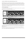
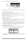
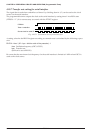
Figure 4.10.6.1 shows the TOUT signal waveform when the channel is changed.
Timer 0 underflow
Timer 1 underflow
CHSEL 0 1
TOUT output (R02)
Fig. 4.10.6.1 TOUT signal waveform at channel change
The TOUT signal can be output from the R02 output port terminal. Programmable clocks can be supplied
to external devices.
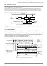
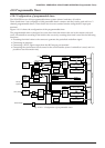
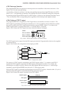
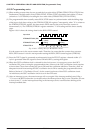
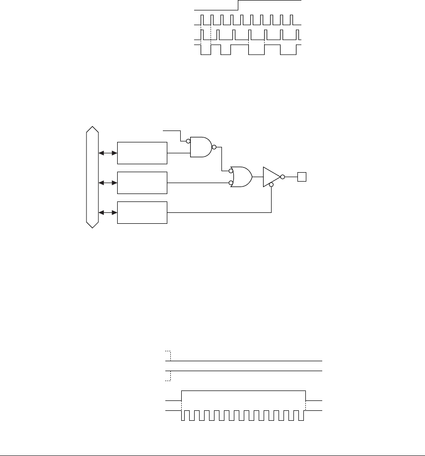
Figure 4.10.6.2 shows the configuration of the output port R02.
Data bus
Register
PTOUT
Register
R02
TOUT
R02
(TOUT)
Register
R02HIZ
Fig. 4.10.6.2 Configuration of R02
The output of a TOUT signal is controlled by the PTOUT register. When "1" is written to the PTOUT
register, the TOUT signal is output from the R02 output port terminal and when "0" is written, the
terminal goes to a high (V
DD) level. However, the data register R02 must always be "1" and the high
impedance control register R02HIZ must always be "0" (data output state).
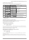
Since the TOUT signal is generated asynchronously from the PTOUT register, a hazard within 1/2 cycle is
generated when the signal is turned ON and OFF by setting the register.
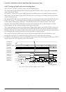
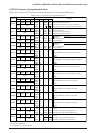
Figure 4.10.6.3 shows the output waveform of the TOUT signal.
R02HIZ register
R02 register
PTOUT register
TOUT output
Fix at "0"
Fix at "1"
"1""0" "0"
Fig. 4.10.6.3 Output waveform of the TOUT signal