


S1C63558 TECHNICAL MANUAL EPSON 79
CHAPTER 4: PERIPHERAL CIRCUITS AND OPERATION (Serial Interface)
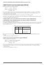
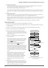
Clock synchronous master mode
In this mode, the internal clock is utilized as a synchronous clock for the built-in shift registers, and 8-
bit clock synchronous serial transfers can be performed with this serial interface as the master.
The synchronous clock is also output from the SCLK terminal which enables control of the external
(slave side) serial I/O device. Since the SRDY terminal is not utilized in this mode, it can be used as an
I/O port.
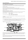
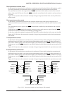
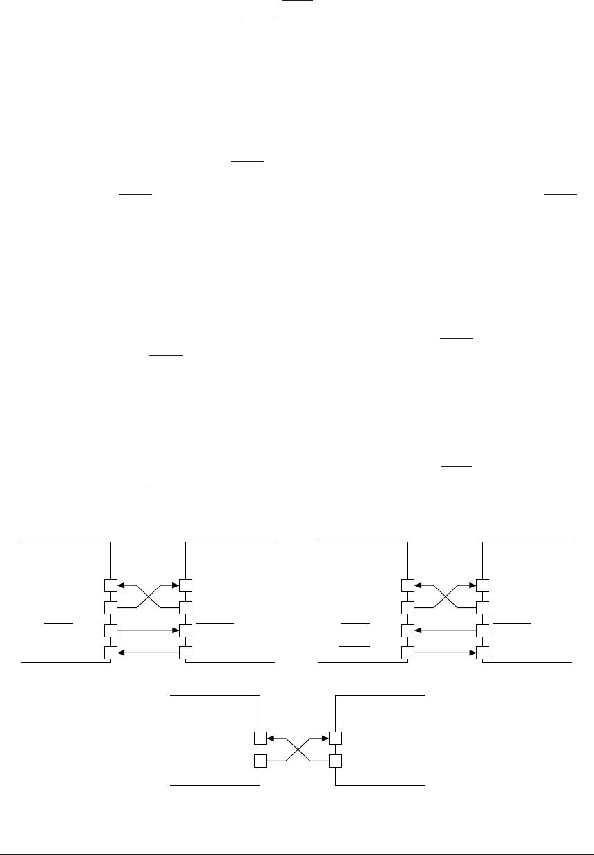
Figure 4.11.3.1(a) shows the connection example of input/output terminals in the clock synchronous
master mode.
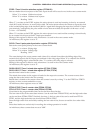
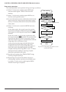
Clock synchronous slave mode
In this mode, a synchronous clock from the external (master side) serial input/output device is
utilized and 8-bit clock synchronous serial transfers can be performed with this serial interface as the
slave.
The synchronous clock is input to the SCLK terminal and is utilized by this interface as the synchro-
nous clock.
Furthermore, the SRDY signal indicating the transmit-receive ready status is output from the SRDY
terminal in accordance with the serial interface operating status.
In the slave mode, the settings for registers SCS0 and SCS1 used to select the clock source are invalid.
Figure 4.11.3.1(b) shows the connection example of input/output terminals in the clock synchronous
slave mode.
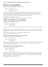
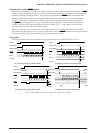
7-bit asynchronous mode
In this mode, 7-bit asynchronous transfer can be performed. Parity check during data reception and
addition of parity bit (odd/even/none) during transmitting can be specified and data processed in 7
bits with or without parity. Since this mode employs the internal clock, the SCLK terminal is not used.
Furthermore, since the SRDY terminal is not utilized either, both of these terminals can be used as I/O
ports.
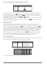
Figure 4.11.3.1(c) shows the connection example of input/output terminals in the asynchronous mode.
8-bit asynchronous 8-bit mode
In this mode, 8-bit asynchronous transfer can be performed. Parity check during data reception and
addition of parity bit (odd/even/none) during transmitting can be specified and data processed in 8
bits with or without parity. Since this mode employs the internal clock, the SCLK terminal is not used.
Furthermore, since the SRDY terminal is not utilized either, both of these terminals can be used as I/O
ports.
Figure 4.11.3.1(c) shows the connection example of input/output terminals in the asynchronous mode.
Data input
Data output
CLOCK input
READY output
SIN(P10)
SOUT(P11)
SCLK(P12)
Input port(Kxx)
External
serial device
S1C63558
(a) Clock synchronous master mode
Data input
Data output
CLOCK output
READY input
SIN(P10)
SOUT(P11)
SCLK(P12)
SRDY(P13)
External
serial device
S1C63558
(b) Clock synchronous slave mode
Data input
Data output
SIN(P10)
SOUT(P11)
External
serial device
S1C63558
(c) Asynchronous 7-bit/8-bit mode
Fig. 4.11.3.1 Connection examples of serial interface I/O terminals