


S1C63558 TECHNICAL MANUAL EPSON 91
CHAPTER 4: PERIPHERAL CIRCUITS AND OPERATION (Serial Interface)
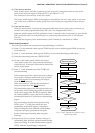
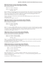
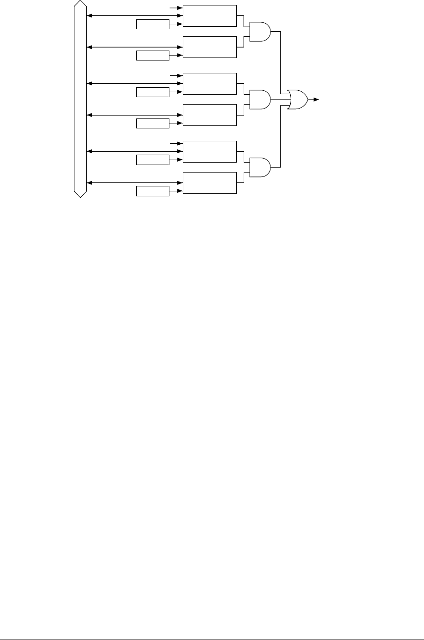
Data bus
Interrupt
request
Address
Error generation
Interrupt factor
flag ISER
Address
Interrupt mask
register EISER
Address
Receive completion
Interrupt factor
flag ISRC
Address
Interrupt mask
register EISRC
Address
Transmit completion
Interrupt factor
flag ISTR
Address
Interrupt mask
register EISTR
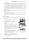
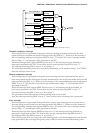
Fig. 4.11.8.1 Configuration of serial interface interrupt circuit
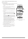
Transmit completion interrupt
This interrupt factor is generated at the point where the sending of the data written into the shift
register has been completed and sets the interrupt factor flag ISTR to "1". When set in this manner, if
the corresponding interrupt mask register EISTR is set to "1" and the CPU is set to interrupt enabled
status (I flag = "1"), an interrupt will be generated to the CPU.
When the interrupt mask register EISTR has been set to "0" and interrupt has been disabled, no
interrupt is generated to the CPU. Even in this case, the interrupt factor flag ISTR is set to "1".
The interrupt factor flag ISTR is reset to "0" by writing "1".
The following transmitting data can be set and the transmitting can be started (writing "1" to TXTRG)
after this interrupt factor occurs.
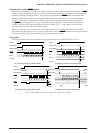
Receive completion interrupt
This interrupt factor is generated at the point where receiving has been completed and the receive
data incorporated into the shift register has been transferred into the receive data buffer and it sets the
interrupt factor flag ISRC to "1". When set in this manner, if the corresponding interrupt mask register
EISRC is set to "1" and the CPU is set to interrupt enabled status (I flag = "1"), an interrupt will be
generated to the CPU.
When the interrupt mask register EISRC has been set to "0" and interrupt has been disabled, no
interrupt is generated to the CPU. Even in this case, the interrupt factor flag ISRC is set to "1".
The interrupt factor flag ISRC is reset to "0" by writing "1".
The generation of this interrupt factor allows reading of the received data.
Also, the interrupt factor flag ISRC is set to "1" when a parity error or framing error is generated.
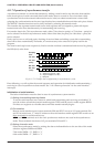
Error interrupt
This interrupt factor is generated at the point where a parity error, framing error or overrun error is
detected during receiving and it sets the interrupt factor flag ISER to "1". When set in this manner, if
the corresponding interrupt mask register EISER is set to "1" and the CPU is set to interrupt enabled
status (I flag = "1"), an interrupt will be generated to the CPU.
When the interrupt mask register EISER has been set to "0" and interrupt has been disabled, an
interrupt is not generated to the CPU. Even in this case, the interrupt factor flag ISER is set to "1".
The interrupt factor flag ISER is reset to "0" by writing "1".
Since all three types of errors result in the same interrupt factor, you should identify the error that has
been generated by the error flags PER (parity error), OER (overrun error) and FER (framing error).