


S1C63558 TECHNICAL MANUAL EPSON 101
CHAPTER 4: PERIPHERAL CIRCUITS AND OPERATION (Sound Generator)
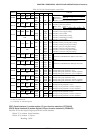
4.12.3 Control of buzzer output
The R01 and R00 terminals for buzzer output are set as general-purpose output ports at initial reset.
Therefore, the R01 terminal must be set as the BZ output terminal by writing "1" to the BZOUT register
before controlling buzzer output. Furthermore, the data register R01 for the R01 output port should be
fixed at "1" and the high-impedance register R01HIZ at "0".
When direct driving a piezoelectric buzzer, the R00 terminal must be set as the XBZ output terminal
similar to the R01 terminal. Write "1" to the XBZOUT register to set the XBZ output. Also in this case, the
data register R00 for the R00 output port should be fixed at "1" and the high-impedance register R00HIZ
at "0".
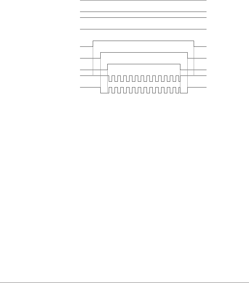
The buzzer signals generated by the sound generator are output from the BZ (R01) and XBZ (R00)
terminals by writing "1" to the buzzer output enable register BZE. When "0" is written to the BZE register,
the BZ (R01) terminal goes High (V
DD) and XBZ (R00) terminal goes Low (VSS).
R01HIZ register
R00HIZ register
R01 register
R00 register
BZOUT register
XBZOUT register
BZE register
R01(BZ) port
R00(XBZ) port
"0"
"0"
"1"
"1"
"1"
"1"
"1"
"0"
"0"
"0"
"0"
"0"
"0"
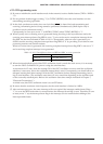
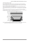
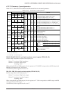
Fig. 4.12.3.1 Buzzer signal output timing chart
Note: Since the BZ and XBZ signals are generated asynchronous to the BZE register, hazards may be
produced when the signal goes ON/OFF due to the setting of the BZE register.