


S1C63558 TECHNICAL MANUAL EPSON 9
CHAPTER 2: POWER SUPPLY AND INITIAL RESET
2.2 Initial Reset
To initialize the S1C63558 circuits, initial reset must be executed. There are two ways of doing this.
(1) External initial reset by the RESET terminal
(2) External initial reset by simultaneous low input to terminals K00–K03 (mask option setting)
The circuits are initialized by either (1) or (2). When the power is turned on, be sure to initialize using the
reset function. It is not guaranteed that the circuits are initialized by only turning the power on.
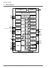
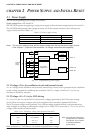
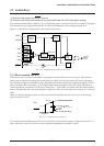
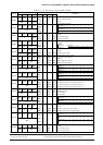
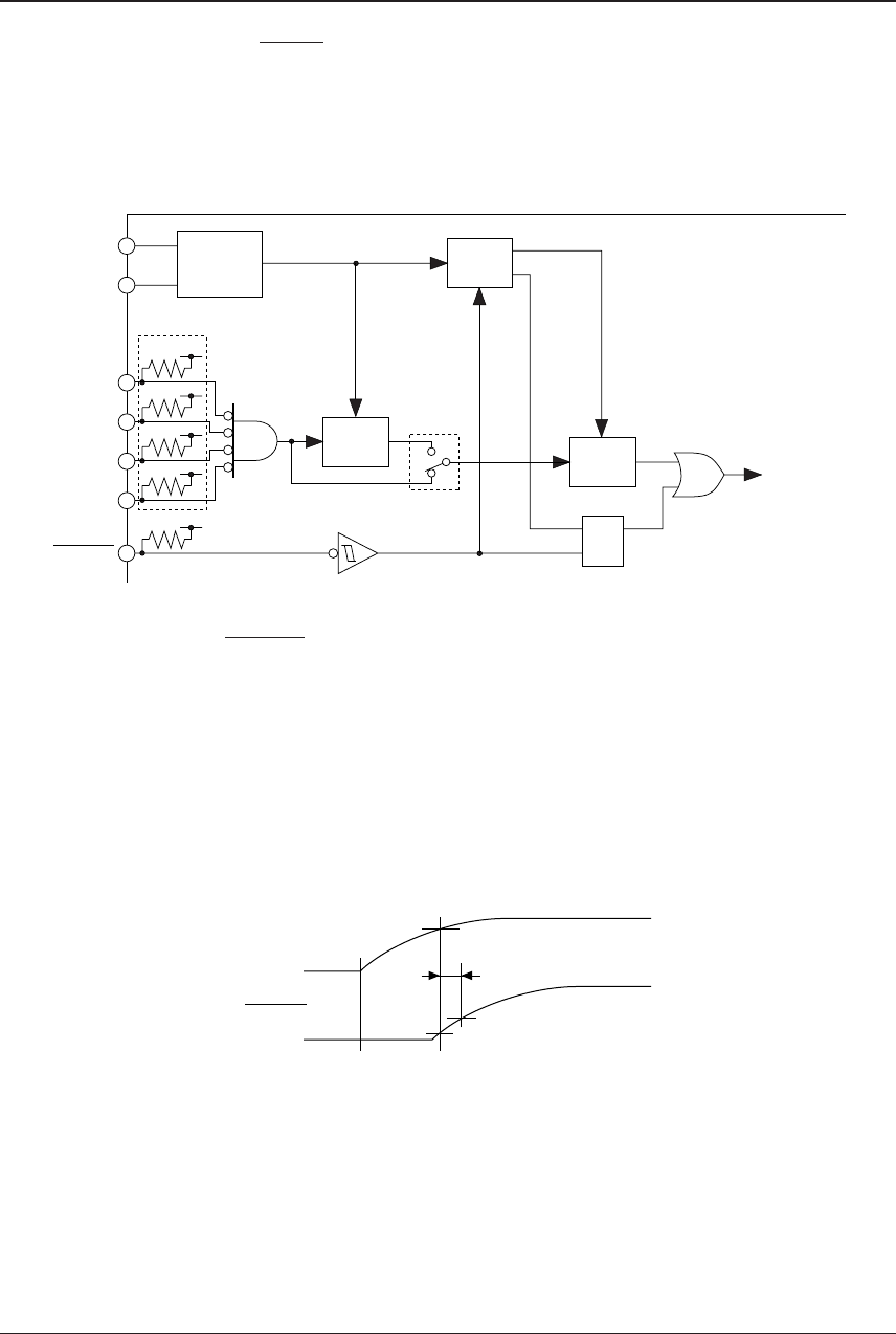
Figure 2.2.1 shows the configuration of the initial reset circuit.
RESET
K00
K01
K02
K03
OSC2
OSC1
RQ
S
Internal
initial
reset
Divider
V
DD
1 Hz
2 Hz
V
DD
OSC1
oscillation
circuit
Noise
reject
circuit
Time
authorize
circuit
Mask option
Mask option
Fig. 2.2.1 Configuration of initial reset circuit
2.2.1 Reset terminal (RESET)
Initial reset can be executed externally by setting the reset terminal to a low level (VSS). After that the
initial reset is released by setting the reset terminal to a high level (V
DD) and the CPU starts operating.
The reset input signal is maintained by the RS latch and becomes the internal initial reset signal. The RS
latch is designed to be released by a 2 Hz signal (high) that is divided by the OSC1 clock. Therefore in
normal operation, a maximum of 250 msec (when f
OSC1 = 32.768 kHz) is needed until the internal initial
reset is released after the reset terminal goes to high level. Be sure to maintain a reset input of 0.1 msec or
more.
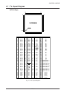
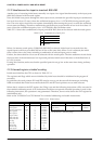
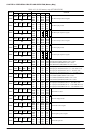
However, when turning the power on, the reset terminal should be set at a low level as in the timing
shown in Figure 2.2.1.1.
VDD
RESET
2.0 msec or more
2.2 V
0.5•V
DD
0.1•V
DD
or less (low level)
Power on
Fig. 2.2.1.1 Initial reset at power on
The reset terminal should be set to 0.1•V
DD or less (low level) until the supply voltage becomes 2.2 V or
more. After that, a level of 0.5•V
DD or less should be maintained more than 2.0 msec.