


78 EPSON S1C63558 TECHNICAL MANUAL
CHAPTER 4: PERIPHERAL CIRCUITS AND OPERATION (Serial Interface)
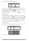
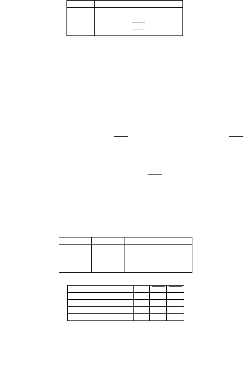
Table 4.11.1.1 Configuration of input/output terminals
Terminal When serial interface is selected
P10
P11
P12
P13
SIN
SOUT
SCLK
SRDY
* The terminals used may vary depending on the transfer mode.
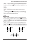
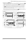
SIN and SOUT are serial data input and output terminals which function identically in clock synchronous
system and asynchronous system. SCLK is exclusively for use with clock synchronous system and func-
tions as a synchronous clock input/output terminal. SRDY is exclusively for use in clock synchronous
slave mode and functions as a send-receive ready signal output terminal.
When asynchronous system is selected, since SCLK and SRDY are superfluous, the I/O port terminals P12
and P13 can be used as I/O ports.
In the same way, when clock synchronous master mode is selected, since SRDY is superfluous, the I/O port
terminal P13 can be used as I/O port.
4.11.2 Mask option
Since the input/output terminals of the serial interface is shared with the I/O ports (P10–P13), the mask
option that selects the output specification for the I/O port is also applied to the serial interface.
The output specification of the terminals SOUT, SCLK (for clock synchronous master mode) and SRDY
(for clock synchronous slave mode) that are used as output in the input/output port of the serial interface
is respectively selected by the mask options of P11, P12 and P13. Either complementary output or N-
channel open drain output can be selected as the output specification. However, when N-channel open
drain output is selected, do not apply a voltage exceeding the power supply voltage to the terminal.
Furthermore, the pull-up resistor for the SIN terminal and the SCLK terminal (for clock synchronous
slave mode) that are used as input terminals can be selected by the mask options of P10 and P12.
When "without pull-up" is selected, take care that the floating status does not occur.
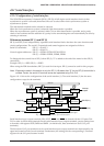
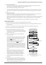
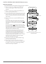
4.11.3 Transfer modes
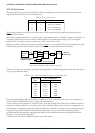
There are four transfer modes for the serial interface and mode selection is made by setting the two bits of
the mode selection registers SMD0 and SMD1 as shown in the table below.
Table 4.11.3.1 Transfer modes
SMD1/SMD1S SMD0/SMD0S Mode
1
1
0
0
1
0
1
0
8-bit asynchronous
7-bit asynchronous
Clock synchronous slave
Clock synchronous master
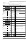
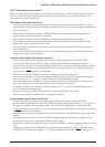
Table 4.11.3.2 Terminal settings corresponding to each transfer mode
Mode SIN
Asynchronous 8-bit
Asynchronous 7-bit
Clock synchronous slave
Clock synchronous master
P13
P13
Output
P13
SOUT SCLK SRDY
P12
P12
Input
Output
Output
Output
Output
Output
Input
Input
Input
Input
At initial reset, transfer mode is set to clock synchronous master mode.