


164 EPSON S1C63558 TECHNICAL MANUAL
CHAPTER 7: ELECTRICAL CHARACTERISTICS
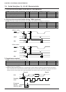
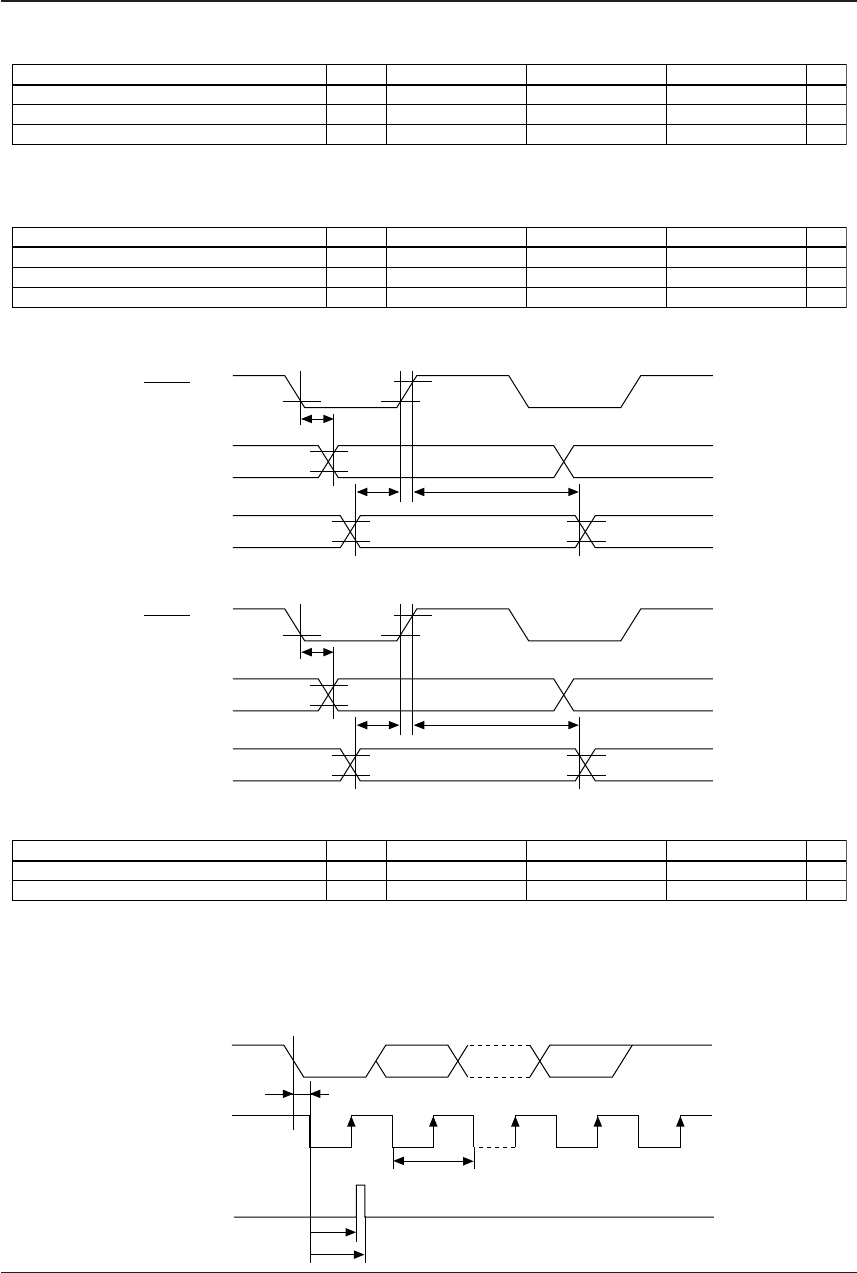
7.6 Serial Interface (1), (2) AC Characteristics
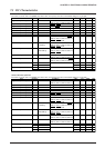
1. Clock synchronous master mode (during 1 MHz operation)
Item
Transmitting data output delay time
Receiving data input set-up time
Receiving data input hold time
Symbol
t
smd
t
sms
t
smh
Unit
ns
ns
ns
Max.
200
Typ.Min.
400
200
Note that the maximum clock frequency is limited to 1 MHz.
Condition: V
DD
=3.0V, V
SS
=0V, Ta=-20 to 70°C, V
IH1
=0.8V
DD
, V
IL1
=0.2V
DD
, V
OH
=0.8V
DD
, V
OL
=0.2V
DD
2. Clock synchronous slave mode (during 1 MHz operation)
Item
Transmitting data output delay time
Receiving data input set-up time
Receiving data input hold time
Symbol
t
ssd
t
sss
t
ssh
Unit
ns
ns
ns
Max.
500
Typ.Min.
400
200
Note that the maximum clock frequency is limited to 1 MHz.
Condition: V
DD
=3.0V, V
SS
=0V, Ta=-20 to 70°C, V
IH1
=0.8V
DD
, V
IL1
=0.2V
DD
, V
OH
=0.8V
DD
, V
OL
=0.2V
DD
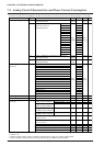
<Master mode>
SCLK OUT
SOUT
SIN
V
OH
V
OH
V
OL
t
sms
t
smh
t
smd
V
IH1
V
IL1
V
OL
<Slave mode>
SCLK IN
SOUT
SIN
V
IH1
V
OH
V
OL
t
sss
t
ssh
t
ssd
V
IH1
V
IL1
V
IL1
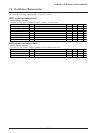
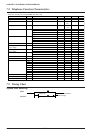
3. Asynchronous system
Item
Start bit detection error time ∗1
Erroneous start bit detection range time ∗2
∗1
∗2
Symbol
t
sa
1
t
sa
2
Unit
s
s
Max.
t
/16
10
t
/16
Typ.Min.
0
9
t
/16
Start bit detection error time is a logical delay time from inputting the start bit until internal sampling begins operating.
(Time as far as AC is excluded.)
Erroneous start bit detection range time is a logical range to detect whether a LOW level (start bit) has been input again
after a start bit has been detected and the internal sampling clock has started. When a HIGH level is detected, the start bit
detection circuit is reset and goes into a wait status until the next start bit. (Time as far as AC is excluded.)
Condition: V
DD
=2.2 to 5.5V, V
SS
=0V, Ta=-20 to 70°C
t
sa
1
t
t
sa
2
SIN
Start bit
Sampling
clock
Erroneous
start bit
detection signal
Stop bit