


S1C63558 TECHNICAL MANUAL EPSON 59
CHAPTER 4: PERIPHERAL CIRCUITS AND OPERATION (Clock Timer)
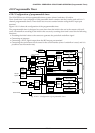
4.8.4 I/O memory of clock timer
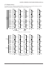
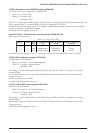
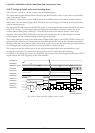
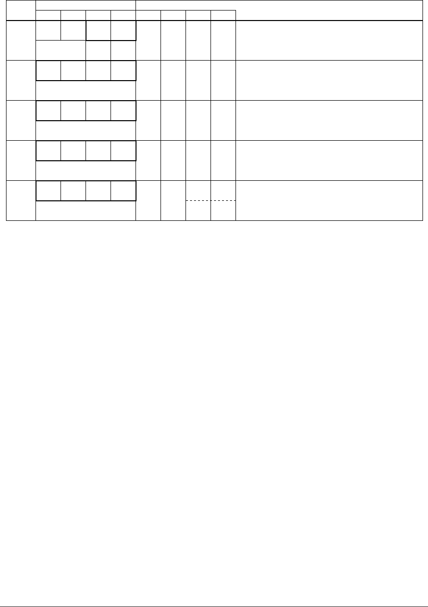
Table 4.8.4.1 shows the I/O addresses and the control bits for the clock timer.
Table 4.8.4.1 Control bits of clock timer
Address Comment
D3 D2
Register
D1 D0 Name Init
∗1
10
W R/WR
FF78H
00TMRST TMRUN
0
∗
3
0
∗
3
TMRST
∗
3
TMRUN
–
∗
2
–
∗
2
Reset
0
Reset
Run
Invalid
Stop
Unused
Unused
Clock timer reset (writing)
Clock timer Run/Stop
R
FF79H
TM3 TM2 TM1 TM0
TM3
TM2
TM1
TM0
0
0
0
0
Clock timer data (16 Hz)
Clock timer data (32 Hz)
Clock timer data (64 Hz)
Clock timer data (128 Hz)
R
FF7AH
TM7 TM6 TM5 TM4
TM7
TM6
TM5
TM4
0
0
0
0
Clock timer data (1 Hz)
Clock timer data (2 Hz)
Clock timer data (4 Hz)
Clock timer data (8 Hz)
FFE6H
EIT3 EIT2 EIT1 EIT0
R/W
EIT3
EIT2
EIT1
EIT0
0
0
0
0
Enable
Enable
Enable
Enable
Mask
Mask
Mask
Mask
Interrupt mask register (Clock timer 1 Hz)
Interrupt mask register (Clock timer 2 Hz)
Interrupt mask register (Clock timer 8 Hz)
Interrupt mask register (Clock timer 32 Hz)
FFF6H
IT3 IT2 IT1 IT0
R/W
IT3
IT2
IT1
IT0
0
0
0
0
(R)
Yes
(W)
Reset
(R)
No
(W)
Invalid
Interrupt factor flag (Clock timer 1 Hz)
Interrupt factor flag (Clock timer 2 Hz)
Interrupt factor flag (Clock timer 8 Hz)
Interrupt factor flag (Clock timer 32 Hz)
*1 Initial value at initial reset
*2 Not set in the circuit
*3 Constantly "0" when being read
TM0–TM7: Timer data (FF79H, FF7AH)
The 128–1 Hz timer data of the clock timer can be read out with these registers. These eight bits are read
only, and writing operations are invalid.
By reading the low-order data (FF79H), the high-order data (FF7AH) is held until reading or for 0.48–1.5
msec (one of shorter of them).
At initial reset, the timer data is initialized to "00H".
TMRST: Clock timer reset (FF78H•D1)
This bit resets the clock timer.
When "1" is written: Clock timer reset
When "0" is written: No operation
Reading: Always "0"
The clock timer is reset by writing "1" to TMRST. When the clock timer is reset in the RUN status, opera-
tion restarts immediately. Also, in the STOP status the reset data is maintained. No operation results
when "0" is written to TMRST.
This bit is write-only, and so is always "0" at reading.
TMRUN: Clock timer RUN/STOP control register (FF78H•D0)
Controls RUN/STOP of the clock timer.
When "1" is written: RUN
When "0" is written: STOP
Reading: Valid
The clock timer enters the RUN status when "1" is written to the TMRUN register, and the STOP status
when "0" is written. In the STOP status, the timer data is maintained until the next RUN status or the
timer is reset. Also, when the STOP status changes to the RUN status, the data that is maintained can be
used for resuming the count.
At initial reset, this register is set to "0".