


62 EPSON S1C63558 TECHNICAL MANUAL
CHAPTER 4: PERIPHERAL CIRCUITS AND OPERATION (Stopwatch Timer)
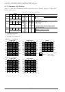
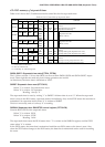
SWD0–SWD3 generates an approximated 10 Hz signal from the basic 256 Hz signal (fOSC1 dividing
clock). The count-up intervals are 2/256 sec and 3/256 sec, so that finally two patterns are generated: 25/
256 sec and 26/256 sec intervals. Consequently, these patterns do not amount to an accurate 1/100 sec.
SWD4–SWD7 counts the approximated 10 Hz signals generated by the 25/256 sec and 26/256 sec inter-
vals in the ratio of 4 : 6, to generate a 1 Hz signal. The count-up intervals are 25/256 sec and 26/256 sec,
which do not amount to an accurate 1/10 sec.
4.9.3 Interrupt function
The stopwatch timers SWD0–SWD3 and SWD4–SWD7, through their respective overflows, can generate
10 Hz (approximate 10 Hz) and 1 Hz interrupts.
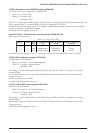
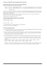
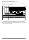
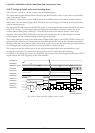
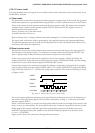
Figure 4.9.3.1 shows the timing chart for the stopwatch timer.
Address
FF7DH
1/100sec
(BCD)
10 Hz Interrupt request
Bit
D0
D1
D2
D3
Stopwatch timer (SWD0–3) timing chart
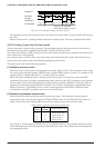
Address
FF7EH
1/10sec
(BCD)
1 Hz Interrupt request
Bit
D0
D1
D2
D3
Stopwatch timer (SWD4–7) timing chart
Fig. 4.9.3.1 Timing chart for stopwatch timer
The stopwatch interrupts are generated by the overflow of their respective counters SWD0–SWD3 and
SWD4–SWD7 (changing "9" to "0"). At this time, the corresponding interrupt factor flags (ISW10 and
ISW1) are set to "1".
The respective interrupts can be masked separately using the interrupt mask registers (EISW10 and
EISW1). However, regardless of the setting of the interrupt mask registers, the interrupt factor flags are
set to "1" by the overflow of their corresponding counters.