


124 EPSON S1C63558 TECHNICAL MANUAL
CHAPTER 4: PERIPHERAL CIRCUITS AND OPERATION (Telephone Function)
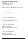
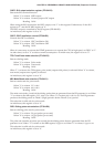
4.14.7 Flash
The flash function pulls down the DP terminal to Low level for a predetermined period of time to
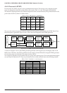
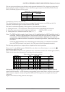
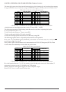
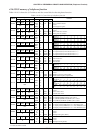
temporarily restore the telephone to on-hook status. The flash time should be set to the FTS3–FTS0
register (FF12H). Table 4.14.7.1 lists the available flash time.
Table 4.14.7.1 Flash time selection
D3
0
0
0
0
0
0
0
0
D2
0
0
0
0
1
1
1
1
D1
0
0
1
1
0
0
1
1
D0
0
1
0
1
0
1
0
1
FTS Flash time
(msec)
Unavailable *
94
188
281
375
469
563
656
D3
1
1
1
1
1
1
1
1
D2
0
0
0
0
1
1
1
1
D1
0
0
1
1
0
0
1
1
D0
0
1
0
1
0
1
0
1
FTS Flash time
(msec)
750
844
938
1031
1125
1219
1313
1406
∗ Do not write "0" (0000B) to the FTS register because it may cause a malfunction.
At initial reset, the flash time is set to 563 msec.
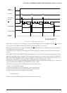
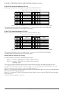
Writing data to the FTS register just defines the flash time. The actual flash operation will be activated
when the FLASH bit (FF14H•D0) is set to "1".
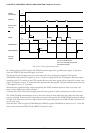
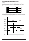
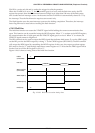
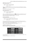
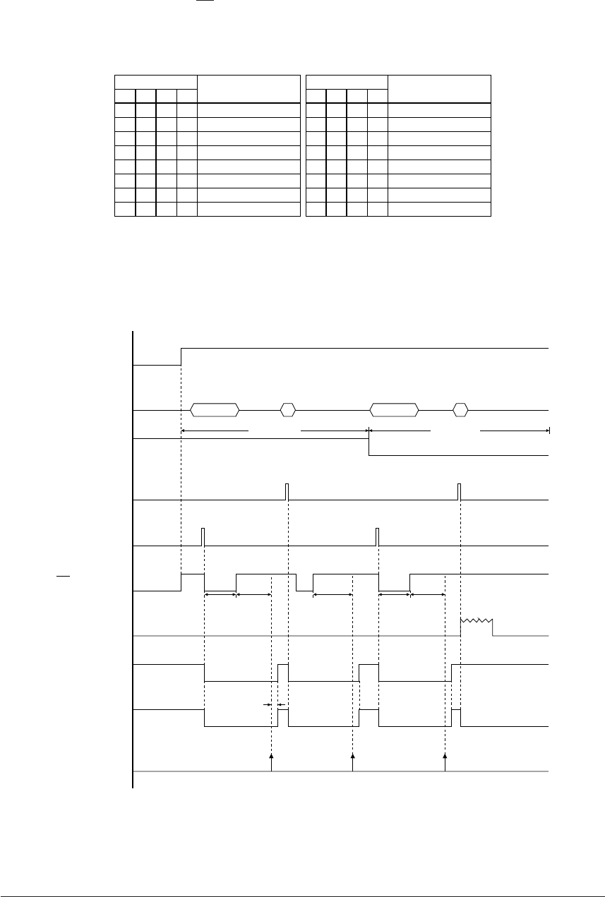
Figure 4.14.7.1 shows a timing chart of the flash function.
tFLP tIDPtFL
"0"
tFL:
tFLP:
tIDP:
tMH:
Flash time
Flash pause time
Inter-digit pause time
Mute hold time
HSON
(FF18H•D3)
Data bus
Write to TPS
(FF10H•D3)
DP
XRMUTE(R11)
XTMUTE(R10)
Interrupt
request
1
Write to FLASH
(FF14H•D0)
TONE
Write to TCD
(FF17H)
Tone modePulse mode
tMH
tFLPtFL
"1"
"0'
"0"
"0"
"0"
"1"
"1"
2
FlashFlash
Fig. 4.14.7.1 Flash execution timing chart