


58 EPSON S1C63558 TECHNICAL MANUAL
CHAPTER 4: PERIPHERAL CIRCUITS AND OPERATION (Clock Timer)
4.8.3 Interrupt function
The clock timer can cause interrupts at the falling edge of 32 Hz, 8 Hz, 2 Hz and 1 Hz signals. Software
can set whether to mask any of these frequencies.
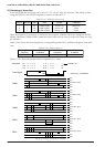
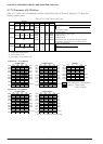
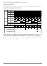
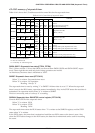
Figure 4.8.3.1 is the timing chart of the clock timer.
Address
FF79H
FF7AH
32 Hz interrupt request
8 Hz interrupt request
2 Hz interrupt request
1 Hz interrupt request
Bit
D0
D1
D2
D3
D0
D1
D2
D3
Frequency Clock timer timing chart
128 Hz
64 Hz
32 Hz
16 Hz
8 Hz
4 Hz
2 Hz
1 Hz
Fig. 4.8.3.1 Timing chart of clock timer
As shown in Figure 4.8.3.1, interrupt is generated at the falling edge of the frequencies (32 Hz, 8 Hz, 2 Hz,
1 Hz). At this time, the corresponding interrupt factor flag (IT0, IT1, IT2, IT3) is set to "1". Selection of
whether to mask the separate interrupts can be made with the interrupt mask registers (EIT0, EIT1, EIT2,
EIT3). However, regardless of the interrupt mask register setting, the interrupt factor flag is set to "1" at
the falling edge of the corresponding signal.