


S1C63558 TECHNICAL MANUAL EPSON 65
CHAPTER 4: PERIPHERAL CIRCUITS AND OPERATION (Programmable Timer)
4.10 Programmable Timer
4.10.1 Configuration of programmable timer
The S1C63558 has two 8-bit programmable timer systems (timer 0 and timer 1) built-in.
Timer 0 and timer 1 are composed of 8-bit presettable down counters and they can be used as 8-bit × 2
channel programmable timers. Timer 0 also has an event counter function using the K13 input port
terminal.
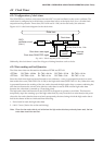
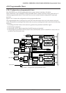
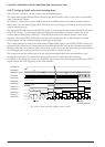
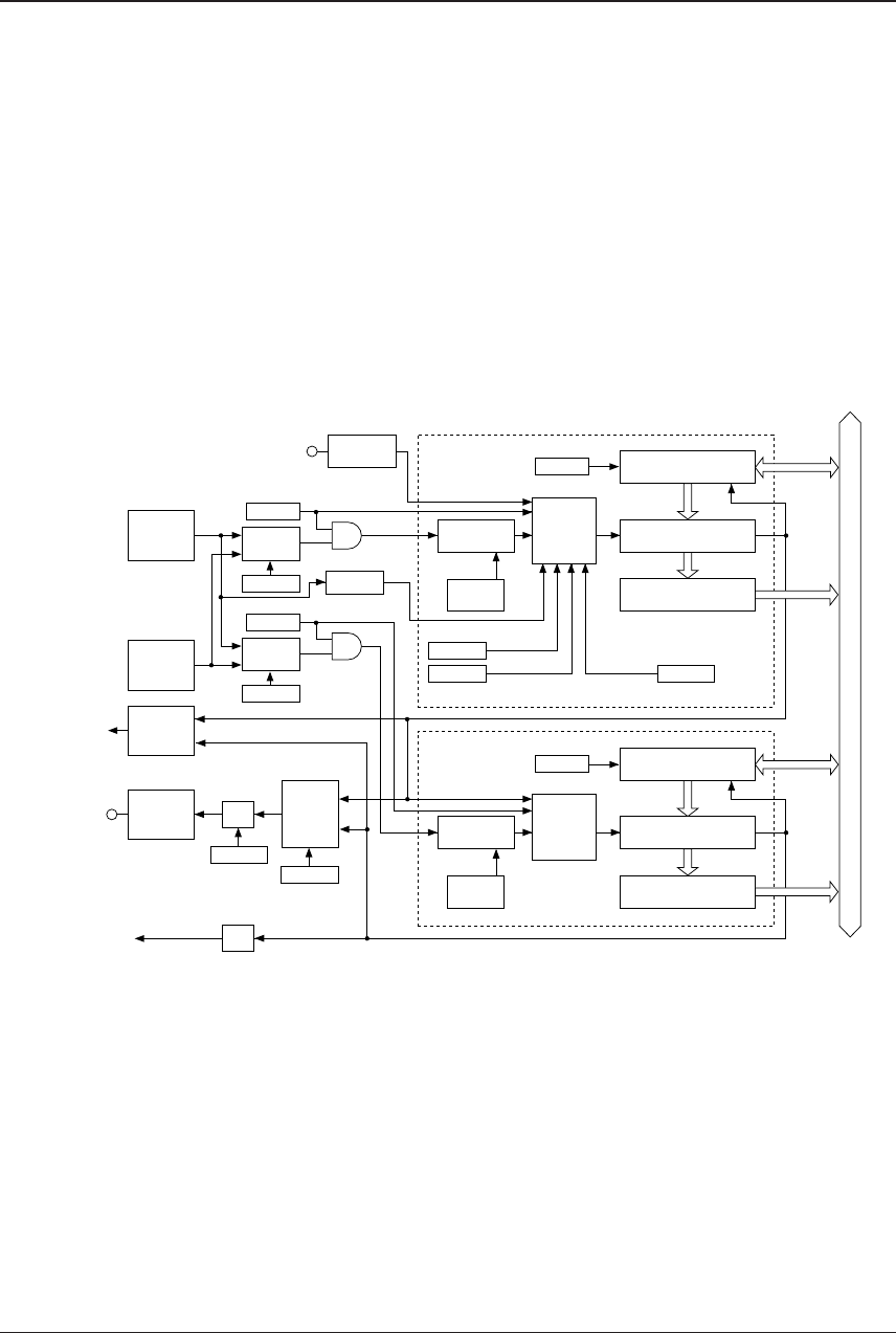
Figure 4.10.1.1 shows the configuration of the programmable timer.
The programmable timer is designed to count down from the initial value set in the counter with soft-
ware. An underflow according to the initial value occurs by counting down and is used for the following
functions:
•Presetting the initial value to the counter to generate the periodical underflow signal
• Generating an interrupt
• Generating a TOUT signal output from the R02 output port terminal
• Generating the synchronous clock source for the serial interface (timer 1 underflow is used, and it is
possible to set the transfer rate)
Reload data register
RLD00–RLD07
Data buffer
PTD00–PTD07
Input port
K13
PTRUN0
FCSEL
PLPOL
Programmable timer 0
PTPS00
PTPS01
8-bit
down counter
Prescaler
Selector
CKSEL0
Timer 0 Run/Stop
Clock
control
circuit
EVCNT
Event counter mode setting
Timer function setting
Pulse polarity setting
Prescaler
setting
Underflow
signal
Data buffer
PTD10–PTD17
Programmable timer 1
PTPS10
PTPS11
8-bit
down counter
Prescaler
Clock
control
circuit
Prescaler
setting
Underflow
signal
Data bus
Interrupt
request
CHSEL
TOUT (R02)
Serial interface
Selector
CKSEL1
Timer 1 Run/Stop
PTRST0
Timer 0 reset
PTRST1
Timer 1 reset
2,048
Hz
Divider
OSC3
oscillation
circuit
Interrupt
control
circuit
OSC1
oscillation
circuit
f
OSC3
f
OSC1
PTRUN1
1/2
PTOUT
Selector
Output port
R02
Reload data register
RLD10–RLD17
1/2
K13
Fig. 4.10.1.1 Configuration of programmable timer