


R
ESTRICTED USE ONLY Fargo Electronics, Inc.
Persona C10/M10 ID Card Printer Service Manual (Rev. 4.0)
103
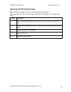
Calibrating the Left Card Sensor
When this part is moved or replaced, the lengthwise print position on cards can be affected.
This sensor provides the precise position of the cards leading edge as it is presented to the
printhead. If the position is incorrect, it may cause ribbon breakage between the yellow and
clear panels of the ribbon.
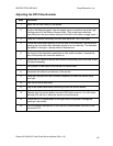
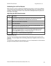
Adjusting the RP3 Potentiometer
Step Procedure
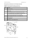
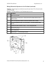
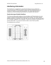
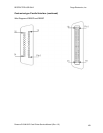
1 Locate RP3 by finding the three small holes on the right-hand side of the
printer; RP3 is located within the third hole down from the top.
2 Install a full-color ribbon in the printer.
3 Run a self test print.
4 Measure the width of the colored bars at each end of the self test print. The
width of each bar should be close to equal.
5 Adjust RP3 counterclockwise in 1/8-turn increments if the green bar on the
leading edge appears thinner. If the red bar on the trailing edge appears
thinner, adjust RP3 clockwise in 1/8-turn increments.
6 Repeat steps 1-7 until the lines are of equal width.
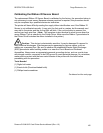
Troubleshooting Tips
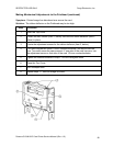
The slots of the Card Sensor may be obscured if the printer behaves as if a card is in the
feed path — the main stepper motor is activating when power is applied and then the on-line
light blinks.
To remove dust or debris from the card sensor, use a can of compressed air to blow between
the upper and lower portions of the Left Card Sensor.