


R
ESTRICTED USE ONLY Fargo Electronics, Inc.
Persona C10/M10 ID Card Printer Service Manual (Rev. 4.0)
151
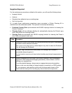
Section 9: Board Level Diagnostics
The purpose of this section to provide the User with specific Board Level Diagnostic
procedures for Board Errors and Sensor Testing for the C10/M10 Card Printer.
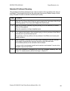
Sensor Testing
Step Procedure
1 Check the voltage to determine if a Sensor is working.
2 a. Test the voltage of each Sensor using ground (GRD = Chassis) to the
correct pin on each connector. See the Sensor Location and Voltages
table on the next page.
b. Block a Slot Sensor with a card.
c. Cover a reflective Sensor with a card.
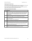
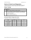
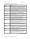
Reviewing the Motor Voltages (when active)
Use this table as a reference tool for Board Level Diagnostics.
Motor Location Pin VDC
Print Drive Stepper J22 4 5
Print Headlift J27 1 17.0
Card Feed J28 4 20
Ribbon Drive J25 2 5