98 SPARC Enterprise T5120 and T5220 Servers Service Manual • July 2009
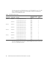
The following table maps FB-DIMM locations with FB-DIMM FRU names. The FRU
name is displayed in memory faults. Use this table to identify the motherboard
location of an FB-DIMM FRU name.
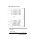
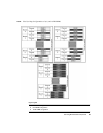
The following figure shows the order in which FB-DIMM slots must be used for the
three level of FB-DIMM quantities.
TABLE: FB-DIMM Installation Map
Branch Name Channel Name FRU Name
Motherboard FB-DIMM
Connector
FB-DIMM
Installation
Order
Branch 3 Channel 1 /SYS/MB/CMP0/BR3/CH1/D1 J2701 3
/SYS/MB/CMP0/BR3/CH1/D0 J2601 2
Channel 0 /SYS/MB/CMP0/BR3/CH0/D1 J2501 3
/SYS/MB/CMP0/BR3/CH0/D0 J2401 1
Branch 2 Channel 1 /SYS/MB/CMP0/BR2/CH1/D1 J2301 3
/SYS/MB/CMP0/BR2/CH1/D0 J2201 2
Channel 0 /SYS/MB/CMP0/BR2/CH0/D1 J2101 3
/SYS/MB/CMP0/BR2/CH0/D0 J2001 1
Branch 0 Channel 0 /SYS/MB/CMP0/BR0/CH0/D0 J1001 1
/SYS/MB/CMP0/BR0/CH0/D1 J1101 3
Channel 1 /SYS/MB/CMP0/BR0/CH1/D0 J1201 2
/SYS/MB/CMP0/BR0/CH1/D1 J1301 3
Branch 1 Channel 0 /SYS/MB/CMP0/BR1/CH0/D0 J1401 1
/SYS/MB/CMP0/BR1/CH0/D1 J1501 3
Channel 1 /SYS/MB/CMP0/BR1/CH1/D0 J1601 2
/SYS/MB/CMP0/BR1/CH1/D1 J1701 3


