110 SPARC Enterprise T5120 and T5220 Servers Service Manual • July 2009
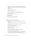
11. Connect the power supplies.
See “Connect Power Cords to the Server” on page 178
Note – As soon as the power cords are connected, standby power is applied.
Depending on how the firmware is configured, the system might boot at this time.
12. Power on the server.
See “Power On the Server Using the poweron Command” on page 179 or “Power
On the Server Using the Front Panel Power Button” on page 180.
Related Information
■ “Remove a PCIe or XAUI Card” on page 106
■ “Remove a PCIe/XAUI Riser” on page 102
■ “Install a PCIe/XAUI Riser” on page 104
PCIe/XAUI Card Configuration Reference for
SPARC Enterprise T5120 Servers
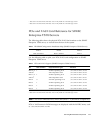
The following table shows the physical PCIe/XAUI slot locations on the SPARC
Enterprise T5120 server, as viewed from the rear of the system.
Use the following table to plan your PCIe/XAUI card configuration on SPARC
Enterprise T5120 server.
TABLE: FB-DIMM Configuration Installation Map (SPARC Enterprise T5220 Servers)
PCIe 0/XAUI 0 PCIe 1/XAUI 1 PCIe 2
TABLE: PCIe and XAUI Support (SPARC Enterprise T5120 Servers)
Slot
PCIe Controller to
Which the Slot is
Connected Supported Device Types FRU Name
PCIe 0 or
XAUI 0
*
1 x8 PCIe operating at x4
XAUI expansion card
/SYS/MB/RISER0/PCIE0
/SYS/MB/RISER0/XAUI0
PCIe 1 or
XAUI 1
†
1 x8 PCIe operating at x4
XAUI expansion card
/SYS/MB/RISER1/PCIE1
/SYS/MB/RISER1/XAUI1
PCIe 2 0 x16 PCIe operating at x8 /SYS/MB/RISER2/PCIE2


