2 SPARC Enterprise T5120 and T5220 Servers Service Manual • July 2009
Infrastructure Boards in SPARC
Enterprise T5120 Servers
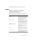
SPARC Enterprise T5120 servers are based on a 1U chassis family. The following
table provides a summary of the circuit boards used in these servers.
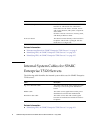
Related Information
■ “Infrastructure Boards in SPARC Enterprise T5220 Servers” on page 3
Board Description
Motherboard This board includes two CMP modules, slots
for 16 FB-DIMM, memory control subsystems,
and all service processor (ILOM) logic. It also
hosts a removable SCC module, which
contains all MAC addresses, host ID, and
ILOM configuration data.
Power distribution board This board distributes main 12V power from
the power supplies to the rest of the system.
This board is directly connected to the paddle
card, and to the motherboard via a bus bar
and ribbon cable. This board also supports a
top cover safety interlock (“kill”) switch.
Paddle card This board serves as the interconnect between
the power distribution board and the fan
power boards, disk drive backplane, and front
I/O board.
Fan power boards (2) These boards carry power to the system fan
modules. In addition, these boards contain fan
module status LEDs and transmit status and
control data for the fan modules.
Hard drive backplane This board includes the connectors for the
hard drives. This board also contains the
interconnect for the front I/O board, Power
and Locator buttons, and system/component
status LEDs.
Each drive has its own Power/Activity, Fault,
and Ready-to-Remove LEDs.
Front I/O board This board connects directly to the hard drive
backplane. This board is packaged with the
DVD drive as a single unit.


