


Chapter 9 Remove/Replace Procedures
84
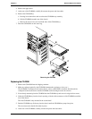
Replacing a Hard Disk Drive (Drive Cage Mounted)
1. If the drive cage is already removed from the chassis, perform the following procedure starting at
Step 3.
2. If it is necessary to remove the drive cage from the chassis, perform steps 3 through 6 of the proceeding
removal procedure.
NOTE If the hard disk drive (HDD) you are planning to install already has a mounting tray
attached, you must remove it before you can install the drive into the drive cage.
3. Make any settings required by the hard disk drive documentation.
For IDE models, the first HDD is set as the IDE master device and the second IDE HDD is set to slave
for the same cable (IDE-1).
For SCSI models, if a termination jumper is set, this jumper must be removed. The SCSI address for the
first HDD is normally set to ID address = 0. The second SCSI HDD is normally set to ID address = 1.
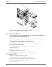
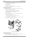
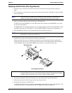
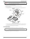
4. Slide the HDD into the drive cage opening with the cable connectors facing you.
NOTE You might find it easier to mount the second optional HDD, if you turn the drive cage
upside down to mount the hard disk drive.
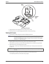
5. Install the four screws to secure the drive to the mass storage cage.
Where you install the screws will depend on which drive you are installing. The first installed drive
(bottom of drive cage) uses two screws on the left side and two screws from bottom on the right side to
secure the HDD. The second optional HDD has four screws, two on each side of the cage.
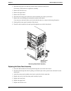
Mounting tabs
Drive Cage Screw Holes
CAUTION All mounting screws used with the hard disk drive must be #6-32 and not exceed ¼-inch
in length. Longer screws may cause internal damage to the mass storage device. Damage
caused by incorrect mounting screws is not covered by the HP warranty.
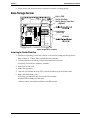
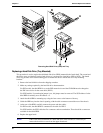
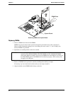
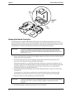
6. If you have installed all of the drives into the drive cage, reinstall drive cage into the chassis.
7. Ensure the tabs at the front on the cage slide into the slots provided.
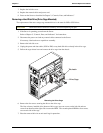
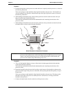
8. Connect the data cable to the disk drive(s).
For the IDE model, use the two connectors on the primary cable (IDE-1) to connect the IDE drives. The
secondary cable (IDE-2) is intended for the IDE CD-ROM and an optional third drive.