


Installing options 97
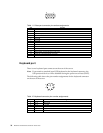
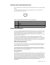
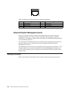
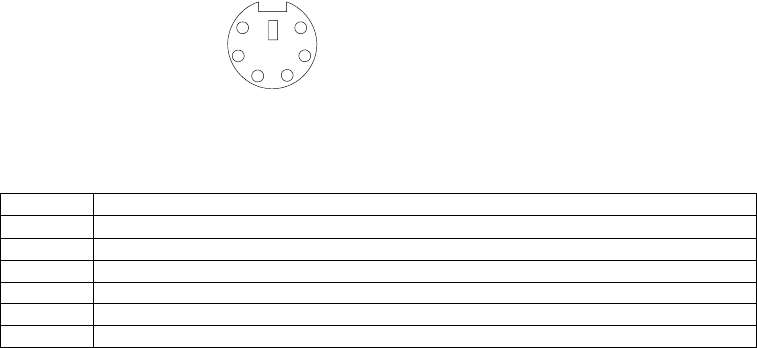
Auxiliary-device (pointing device) port
The I/O board has one auxiliary-device port that supports a mouse or other pointing
device.
The following table shows the pin-number assignments for the auxiliary-device
connector on the rear of the server.
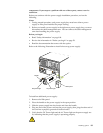
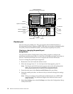
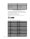
Ultra2 (LVD) SCSI ports
The server supports an optional IBM ServeRAID controller. This controller provides
three independent SCSI channels. A 16-bit (wide) LVD SCSI cable connects the hard
disk drive backplane to one channel of the RAID controller. Two 68-pin SCSI
connectors for two additional channels are on the rear of the server. Refer to “Using
IBM ServeRAID” on page 117.
The server has a dual-channel Ultra-2 small computer system interface (SCSI)
controller. This controller supports two independent SCSI channels: one external and
one internal. Each of these channels supports up to 15 SCSI devices. You can use the
external LVD SCSI channel connector, on the rear of the server, to connect different
types of SCSI devices, such as drives or printers.
SCSI cabling requirements
If you plan to attach external SCSI devices, you must order additional SCSI cables. To
select and order the correct cables for use with external devices, contact your IBM
reseller or IBM marketing representative.
For information about the maximum length of SCSI cable between the terminated
ends of the cable, refer to the ANSI SCSI standards. Adhering to these standards will
help ensure that the server operates properly.
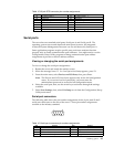
Setting SCSI IDs
Each SCSI device connected to a SCSI controller must have a unique SCSI ID. This ID
enables the SCSI controller to identify the device and ensure that different devices on
the same SCSI channel do not attempt to transfer data simultaneously. SCSI devices
that are connected to different SCSI channels can have duplicate SCSI IDs. SCSI IDs 6
and 7 are reserved for the SCSI controller on either SCSI channel A or B. The following
table lists the SCSI IDs for devices that are connected to one channel. In Table 14 on
page 98, the hot-swap hard disk drive bays are in the standard (vertical)
configuration.
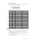
Table 13. Auxiliary-device connector pin-number assignments .
Pin Signal
1Data
2 Not connected
3Ground
4+5 V dc
5Clock
6 Not connected
6
4
2
1
3
5