


Installing options 57
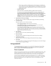
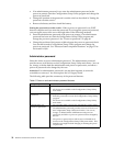
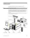
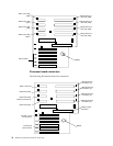
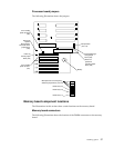
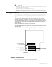
Processor board jumpers
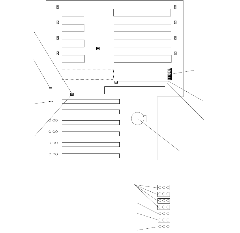
The following illustration shows the jumpers.
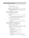
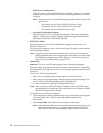
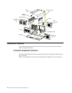
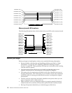
Memory board component locations
The illustrations in this section show certain locations on the memory board.
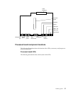
Memory board connectors
The following illustration shows the location of the DIMM connectors on the memory
board.
Jumper block
(J10-J16)
Flash ROM page-
swap jumper
block (J56)
Power-on
password
override jumper
block (J48)
Battery
Advanced
System
Management
Processor reset
jumper block
(J59)
Power-on
control jumper
block (J23)
3.3 V standby
power for slot 2
(J20)
3.3 V standby
power for slot 1
(J47)
Microprocessor core-frequency
selection jumper block (J13-J16)
Reserved (J10)
Reserved (J12)
Reserved (J11)