


58 Hardware Maintenance Manual: xSeries 250
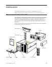
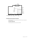
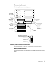
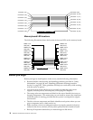
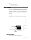
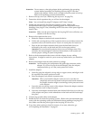
Memory board LED locations
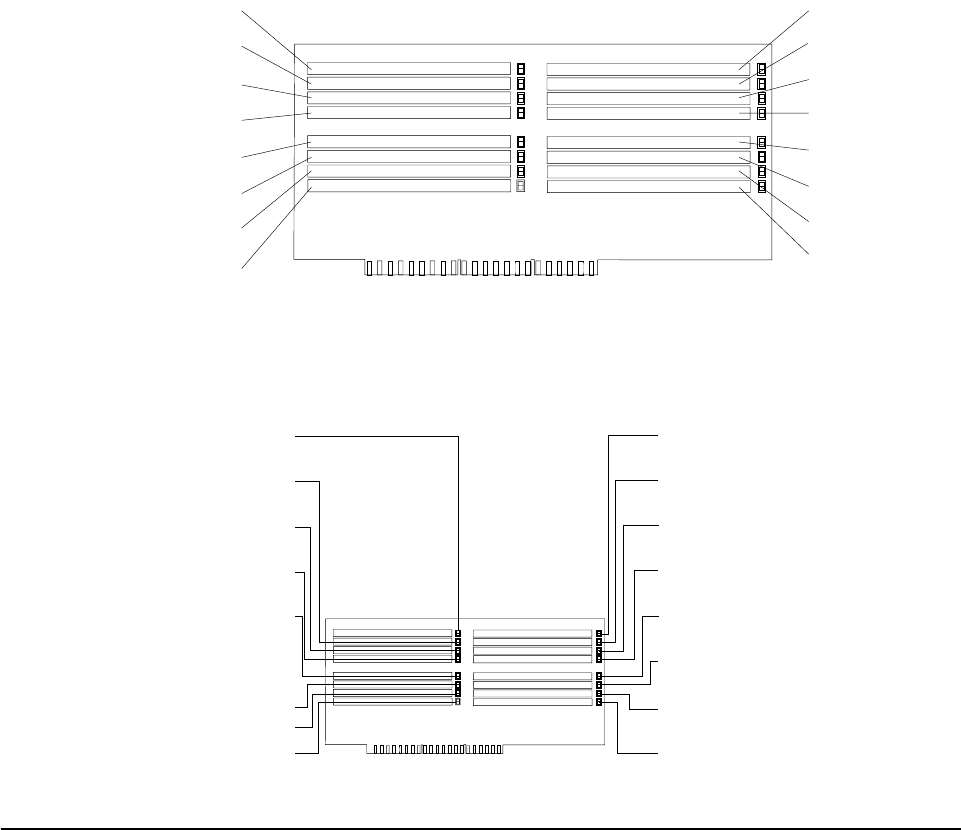
The following illustration shows the location of the error LEDs on the memory board.
Before you begin
Before you begin to install options in the server, read the following information:
• Become familiar with the safety and handling guidelines provided in “Safety
information” on page 180, and “Handling electrostatic discharge-sensitive
devices” on page 183. These guidelines will help you work safely while working
with the server or options.
• You do not need to turn off the server to install or replace hot-swap power
supplies, hot-swap drives, hot-swap fans, or hot-plug PCI adapters.
• The orange color on components and labels in the server identifies hot-swap or
hot-plug components. This means that you can install or remove the component
while the system is running, provided that the system is configured to support
this function.
• The blue color on components and labels identifies touch points where you can
grip a component, move a latch, and so on.
• Make sure that you have an adequate number of properly grounded electrical
outlets for the server, monitor, and any other options that you intend to install.
• Back up all important data before you make changes to disk drives.
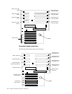
Connector 1(J1) Connector 9 (J9)
Connector 10 (J10)
Connector 11 (J11)
Connector 12 (J12)
Connector 13 (J13)
Connector 14 (J14)
Connector 15 (J15)
Connector 16 (J16)
Connector 2 (J2)
Connector 3 (J3)
Connector 4 (J4)
Connector 5 (J5)
Connector 6 (J6)
Connector 7 (J7)
Connector 8 (J8)
DIMM 1 error
LED (CR4)
DIMM 9 error
LED (CR13)
DIMM 2 error
LED (CR5)
DIMM 10 error
LED (CR12)
DIMM 3 error
LED (CR2)
DIMM 11 error
LED (CR15)
DIMM 4 error
LED (CR1)
DIMM 12 error
LED (CR16)
DIMM 5 error
LED (CR6)
DIMM 13 error
LED (CR11)
DIMM 6 error
LED (CR3)
DIMM 14 error
LED (CR14)
DIMM 7 error
LED (CR7)
DIMM 15 error
LED (CR10)
DIMM 8 error
LED (CR8)
DIMM 16 error
LED (CR9)