


56 Hardware Maintenance Manual: xSeries 250
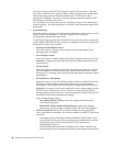
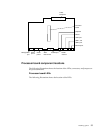
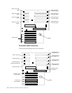
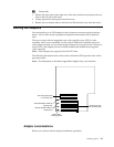
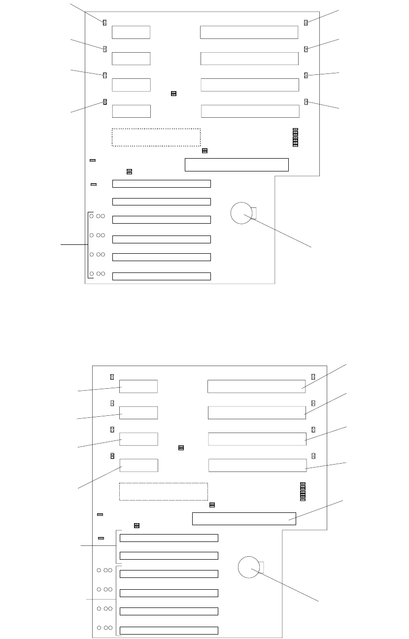
Processor board connectors
The following illustration shows the connectors.
Microprocessor 2
error LED (Cr3)
Microprocessor 1
error LED (Cr9)
Microprocessor 3
error LED (Cr8)
Microprocessor 4
error LED (Cr4)
Battery
VRM 1 error LED
VRM 4 error LED
VRM 3 error LED
VRM 2 error LED
C
R6
C
C
R7
R5
(
(
(
)
C
R3
()
C
R8
()
C
R9
()
)
)
C
R10
()
C
R4
()
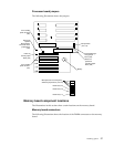
PCI slot LEDs
Microprocessor 2
Connector (J3)
Microprocessor 1
Connector (J2)
Microprocessor 3
Connector (J4)
Microprocessor 4
Connector (J5)
Battery
VRM 1 Connector
VRM 4 Connector
VRM 3 Connector
Reserved (J8 and J9)
VRM 2 Connector
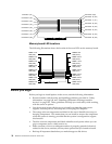
Memory board
Connector
PCI Slot 1 and 2
(on PCI bus A)
PCI Slot 3-6
(on PCI bus B)