


Installing options 87
processor 3; a microprocessor installed in microprocessor connector J5 is
processor 4. If more than one microprocessor is installed, the highest numbered
processor is the one the server will start from. The lower numbered
microprocessors are used as application processors.
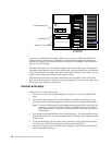
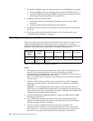
The following table and the label on the inside of the top cover of the server show the
order in which additional microprocessors and voltage regulator modules (VRMs)
must be installed.
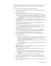
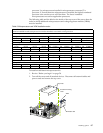
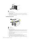
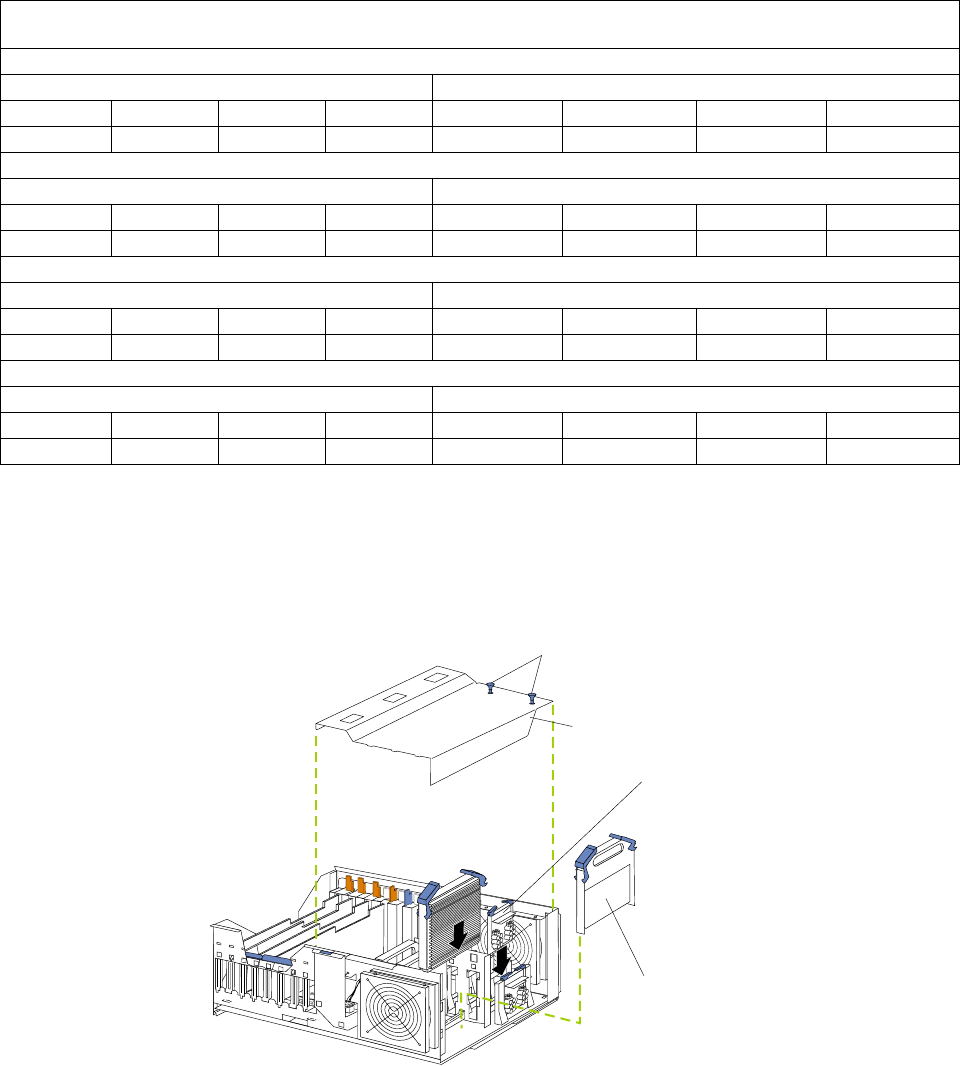
To install an additional microprocessor kit:
1. Review “Before you begin” on page 58.
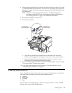
2. Turn off the server and all attached devices. Disconnect all external cables and
power cords and remove the top cover.
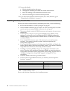
Table 9. Microprocessor and VRM installation order.
Note: "T" indicates an installed terminator card; "X" indicates an installed microprocessor or VRM. A terminator card
must be installed in each microprocessor connector that does not contain a microprocessor.
One microprocessor installed
Microprocessor connectors VRM connectors
J2 (P1) J3 (P2) J4 (P3) J5 (P4) J37 (VRM 1) J38 (VRM 2) J39 (VRM 3) J41 (VRM 4)
XTTT X
Two microprocessors installed
Microprocessor connectors VRM connectors
J2 (P1) J3 (P2) J4 (P3) J5 (P4) J37 (VRM 1) J38 (VRM 2) J39 (VRM 3) J41 (VRM 4)
XXTT X X
Three microprocessors installed
Microprocessor connectors VRM connectors
J2 (P1) J3 (P2) J4 (P3) J5 (P4) J37 (VRM 1) J38 (VRM 2) J39 (VRM 3) J41 (VRM 4)
XXXT X X X
Four microprocessors installed
Microprocessor connectors VRM connectors
J2 (P1) J3 (P2) J4 (P3) J5 (P4) J37 (VRM 1) J38 (VRM 2) J39 (VRM 3) J41 (VRM 4)
XXXXXXXX
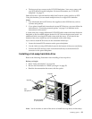
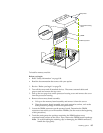
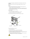
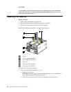
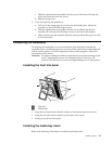
Pop rivets
Terminator card
VRM
Processor housing
cover