


84 Hardware Maintenance Manual: xSeries 250
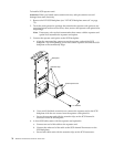
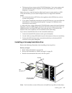
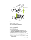
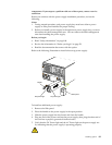
13. Connect the shuttle.
a. Slide the shuttle back into the server
b. Disengage the retaining levers from the notches on the chassis.
c. Move the retaining levers toward the front of the server.
d. Secure the retaining levers in the horizontal position.
14. If you have other options to install or remove, do so now; otherwise, go to
“Completing the installation” on page 91.
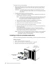
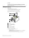
Installing memory-module kits
Before you continue with the memory-installation procedure, review the following:
• Review the information in “Before you begin” on page 58.
• All the DIMMs installed in each set must be the same size and speed, but all the
sets do not have to contain DIMMs of the same size and speed.
• The memory board contains 16 DIMM connectors and supports 4-way memory
interleaving.
• Install only 3.3 V, 168-pin, 8-byte, registered DIMMs. Only 100 MHz, 72-bit,
registered, synchronous, error correcting code (ECC), SDRAM configuration
DIMM memory is supported for the 128 MB, 256 MB, 512 MB and 1 GB (when
available) DIMMs.
• If you install 4 GB of memory, some of the memory is reserved for system
resources. The amount reserved for system resources depends on the
configuration of the server.
• If you install 16 GB of memory, the Configuration/Setup Utility will display the
memory that is usable by the network operating system. This amount of memory
might differ from the amount of memory you have installed.
• Installing or removing DIMMs changes the configuration information in the
server. Therefore, after installing or removing a DIMM, you must save the new
configuration information in the Configuration/Setup Utility program. Refer to
“Using the Configuration/Setup Utility program” on page 45 for more
information.
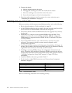
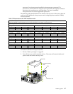
• Install the DIMMs in the order provided in Table 7.
• For the locations of the DIMM connectors, see “Memory board component
locations” on page 57.
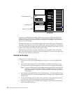
Refer to the following illustration when installing memory.
Set of 4 DIMMs Install DIMMs in these connectors:
First set (shipped as standard) J1, J5, J9, J13
2nd set J2, J6, J10, J14
3rd set J3, J7, J11, J15
4th set J4, J8, J12, J16
Table 7. DIMM installation order.