


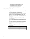
88 Hardware Maintenance Manual: xSeries 250
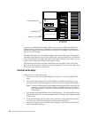
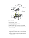
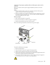
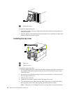
3. Pull up the two pop rivets on the processor housing cover and remove the cover
from the processor housing.
4. Determine the slots where you will install the microprocessor and VRM.
5. Remove the terminator card from the microprocessor connector.
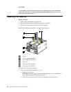
6. Install the microprocessor:
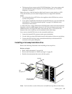
a. Touch the static-protective package containing the new microprocessor to any
unpainted metal surface on the server; then, remove the microprocessor from
the package.
b. Hold the microprocessor by the open latches, and center the microprocessor
over the microprocessor connector.
Attention: Make sure the microprocessor is oriented and aligned correctly
before you try to close the latches.
c. Carefully close the latches to seat the microprocessor in the connector.
d. Store the terminator card in a safe place in the static-protective package that
the new microprocessor comes in; you will need to install it again if you ever
remove the microprocessor.
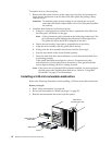
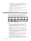
7. Install the voltage regulator module (VRM):
a. Center the VRM over the connector. Make sure that the VRM is oriented and
aligned correctly.
Note: If you remove the microprocessor later, remember to install the
terminator card in the appropriate microprocessor connector and to
remove the VRM for that microprocessor.
b. Carefully close the latches to seat the VRM in the connector.
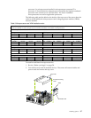
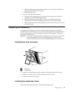
8. Install the processor housing cover and push down on the two pop rivets.
9. If you have other options to install or remove, do so now; otherwise, go to
“Completing the installation” on page 91.
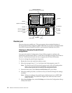
Installing a hot-swap power supply
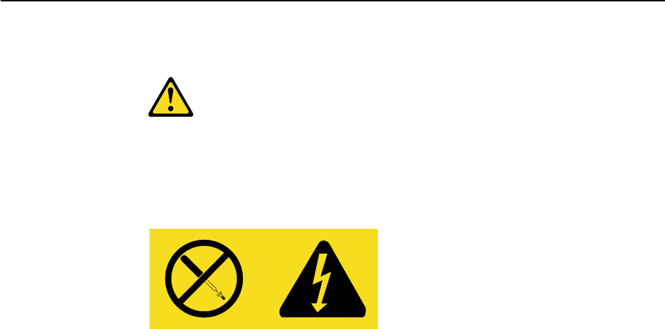
CAUTION:
Never remove the cover on a power supply or any part that has the following label
attached.
Hazardous voltage, current, and energy levels are present inside any component
that has this label attached. There are no serviceable parts inside these