


Installing options 99
Serial ports
The server has two standard serial ports: Serial port A and Serial port B. The
operating system can use and share both serial ports; however, the integrated
Advanced System Management Processor can use and share only Serial port A.
Some application programs require specific ports, and some modems function
properly only at certain communication port addresses. You might need to use the
Configuration/Setup Utility program to change communication port address
assignments to prevent or resolve address conflicts.
Viewing or changing the serial-port assignments
To view or change the serial-port assignments:
1. Restart the server and watch the monitor screen.
2. When the message Press F1 for Configuration/Setup appears, press F1.
3. From the main menu, select Devices and I/O Ports; then, press Enter.
Note: The Devices and I/O Ports choice appears only on the full configuration
menu. If you set two levels of passwords, you must enter the
administrator password to access the full configuration menu.
4. Select the serial port; then, use the arrow keys to advance through the settings
available.
5. Select Save Settings; then, select Exit Setup to exit from the Configuration/Setup
Utility main menu.
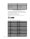
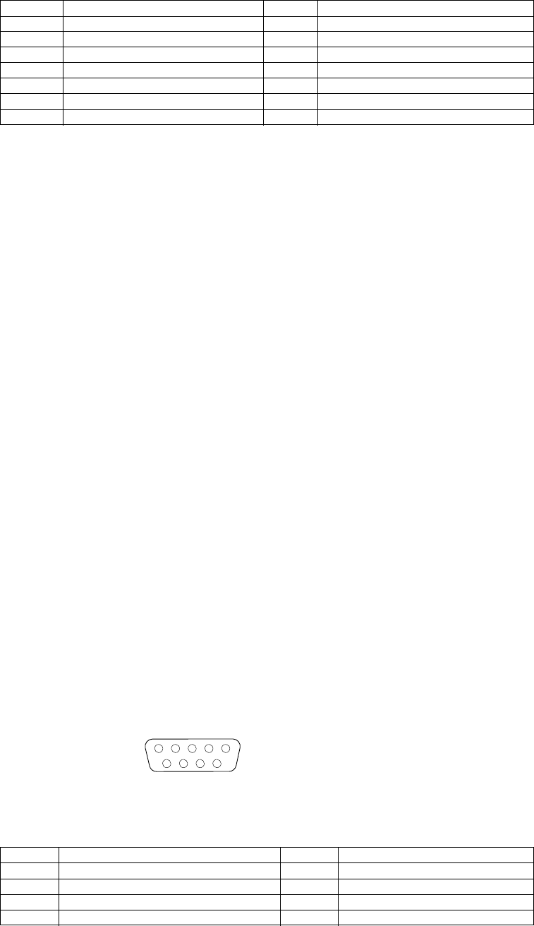
Serial-port connectors
The following table shows the pin-number assignments for the 9-pin, male D-shell
serial-port connectors on the rear of the server. These pin-number assignments
conform to the industry standard.
28 +Control/Data 62 -Control/Data
29 +Request 63 -Request
30 +Input/Output 64 -Input/Output
31 +Data 8 65 -Data 8
32 +Data 9 66 -Data9
33 +Data 10 67 -Data 10
34 +Data 11 68 -Data 11
Table 16. Serial-port connectors pin-number assignments.
Pin Signal Pin Signal
1 Data carrier detect 6 Data set ready
2 Receive data 7 Request to send
3 Transmit data 8 Clear to send
4 Data terminal ready 9 Ring indicator
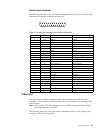
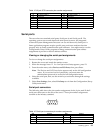
Table 15. 68-pin SCSI connector pin-number assignments.
Pin Signal Pin Signal
1
5
69