


82575 Ethernet Controller Design Guide
4
• If Maximum Link Width = x2, then the 82575 Ethernet Controller negotiates to
either x2 or x1
• If Maximum Link Width = x1, then the 82575 Ethernet Controller only negotiates to
x1
2.3.2 Polarity Inversion
If polarity inversion is detected the Receiver must invert the received data.
During the training sequence, the Receiver looks at Symbols 6-15 of TS1 and TS2 as
the indicator of lane polarity inversion (D+ and D- are swapped). If lane polarity
inversion occurs, the TS1 Symbols 6-15 received will be D21.5 as opposed to the
expected D10.2. Similarly, if lane polarity inversion occurs, Symbols 6-15 of the TS2
ordered set will be D26.5 as opposed to the expected D5.2. This provides the clear
indication of lane polarity inversion.
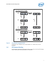
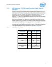
2.3.3 Lane Reversal
The following lane reversal modes are supported (see Figure below):
• Lane configuration of x4, x2, and x1
• Lane reversal in x4 and in x2
• Degraded mode (downshift) from x4 to x2 to x1 and from x2 to x1, with one
restriction - if lane reversal is executed in x4, then downshift is only to x1 and not
to x2.
These restrictions require that a x2 interface to the 82575 Ethernet Controller must
connect to lanes 0 &1 on the 82575 Ethernet Controller. The PCI Express Card
Electromechanical specification does not allow routing a x2 link to a wider connector.
Therefore, the system designer is not allowed to connect a x2 link to lanes 2 and 3 of a
PCI Express connector. It is also recommended that, when using x2 mode on a network
interface card, the 82575 Ethernet Controller be connected to lanes 0 & 1 of the card.