


37
82575 Ethernet Controller Design Guide
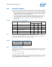
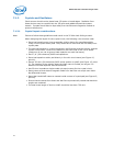
6.0 Oscillator Support
The 82575 clock input circuit is optimized for use with an external crystal. However, an
oscillator can also be used in place of the crystal with the proper design considerations:
• The clock oscillator has an internal voltage regulator of 1.2 V to isolate it from the
external noise of other circuits to minimize jitter. If an external clock is used, this
imposes a maximum input clock amplitude of 1.2 V.
• The input capacitance introduced by the 82575 (approximately 20 pF) is greater
than the capacitance specified by a typical oscillator (approximately 15 pF).
• The input clock jitter from the oscillator can impact the 82575 clock and its
performance.
Note: The power consumption of additional circuitry equals about 1.5 mW.
The following table lists oscillators that have been used successfully in past designs
(please note that no particular product is recommended):
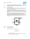
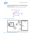
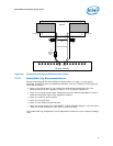
6.1 Oscillator Solution
This solution involves capacitor C1, which forms a capacitor divider with C
stray
of about
20 pF. This attenuates the input clock amplitude and adjusts the clock oscillator load
capacitance.
V
in
= VDD * (C1/(C1 + C
stray
))
V
in
= 3.3 * (C1/(C1 + C
stray
))
This enables load clock oscillators of 15 pF to be used. If the value of C
stray
is unknown,
C1 should be adjusted by tuning the input clock amplitude to approximately 1 V
ptp
. If
C
stray
equals 20 pF, then C1 is 10 pF ±10%.
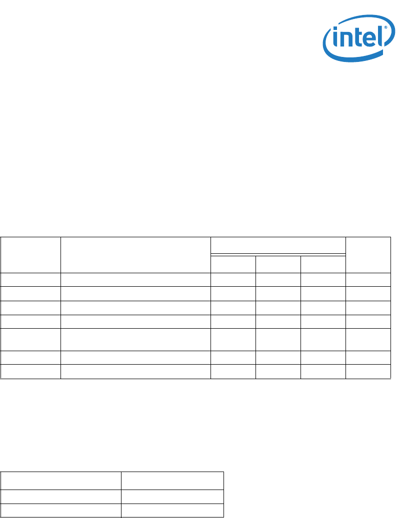
Table 8. 82575 Clock Oscillator Specifications
Symbol Parameter
Specifications
Units
Min Typical Max
f0 Frequency (@25°C) - 25 - MHz
Vp-p External Oscillator Supply Swing 3.0 3.3 3.6 V
Vscp-p XTAL1 Swing 1.1 1.2 1.3 V
Df/f
o
Frequency Tolerance (@ -20 to +70 °C) - ±50 ppm
Topr Operating Temperature -
-20 to
+70
°C
Δf/f
o
Aging - ±5 ppm/year
Ccoupling Coupling Capacitor 8 10 12 pF
Table 9. Oscillator Manufacturers and Part Numbers
Manufacturer Part No.
RALTRON CO4305-25.000-TR
CITIZEN AMERICA CORP CSX750FBB25.000MTR