


33
82575 Ethernet Controller Design Guide
Note: Crystals also carry other specifications for storage temperature, shock resistance, and
reflow solder conditions. Crystal vendors should be consulted early in the design cycle
to discuss the application and its environmental requirements.
5.5 Calibration Mode
The terms “series-resonant” and “parallel-resonant” are often used to describe crystal
oscillator circuits. Specifying parallel mode is critical to determining how the crystal
frequency is calibrated at the factory.
A crystal specified and tested as series resonant oscillates without problem in a
parallel-resonant circuit, but the frequency is higher than nominal by several hundred
parts per million. The purpose of adding load capacitors to a crystal oscillator circuit is
to establish resonance at a frequency higher than the crystal’s inherent series resonant
frequency.
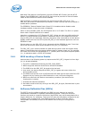
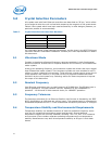
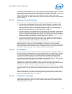
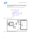
Figure 3 illustrates a simplified schematic of the internal oscillator circuit. Pin X1 and X2
refers to XTAL1 and XTAL2 in the Ethernet device, respectively. The crystal and the
capacitors form a feedback element for the internal inverting amplifier. This
combination is called parallel-resonant, because it has positive reactance at the
selected frequency. In other words, the crystal behaves like an inductor in a parallel LC
circuit. Oscillators with piezoelectric feedback elements are also known as “Pierce”
oscillators.
Figure 9. Internal Oscillator Circuit
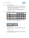
5.6 Load Capacitance
The formula for crystal load capacitance is as follows:
where C1 = C2 = 27 pF
and C
stray
= allowance for additional capacitance in pads, traces and the chip
carrier within the Ethernet device package
Pin X1 Pin X2
Y1
25 MHz
C1
27 pF
5%
C2
27 pF
5%
C
L
C1 C2⋅()
C1 C2+()
-------------------
C
stray
+=