


82575 Ethernet Controller Design Guide
46
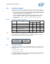
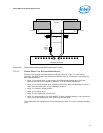
7.1.6.1 Signal Detect
Each port of the 82575 controller has a Signal Detect pin for connection to optical
transceivers. For designs without optical transceivers, these signals can be left
unconnected because they have internal pull-up resistors. Signal Detect is not a high-
speed signal and does not require special layout.
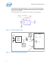
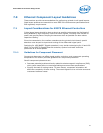
7.1.7 Routing 1.8 V to the Magnetics Center Tap
The central-tap 1.8 V should be delivered as a solid supply plane (1.8 V) directly to the
magnetic module or, if this is not possible, by a short and thick trace (lower than
0.2ohm DC resistance). The decoupling capacitors for the central tap pins should be
placed as close as possible to the magnetic component. This improves both EMI and
IEEE compliance.
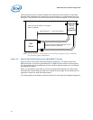
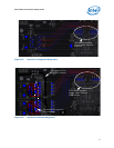
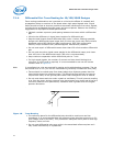
7.1.8 Impedance Discontinuities
Impedance discontinuities cause unwanted signal reflections. Minimize vias (signal
through holes) and other transmission line irregularities. If vias must be used, a
reasonable budget is two per differential trace. Unused pads and stub traces should
also be avoided.
7.1.9 Reducing Circuit Inductance
Traces should be routed over a continuous reference plane with no interruptions. If
there are vacant areas on a reference or power plane, the signal conductors should not
cross the vacant area. This causes impedance mismatches and associated radiated
noise levels. Noisy logic grounds should be separated from analog signal grounds to
reduce coupling. Noisy logic grounds can sometimes affect sensitive DC subsystems
such as analog to digital conversion, operational amplifiers, etc. All ground vias should
be connected to every ground plane; and similarly, every power via, to all power planes
at equal potential. This helps reduce circuit inductance. Another recommendation is to
physically locate grounds to minimize the loop area between a signal path and its
return path. Rise and fall times should be as slow as possible. Because signals with fast
rise and fall times contain many high frequency harmonics, which can radiate
significantly. The most sensitive signal returns closest to the chassis ground should be
connected together. This will result in a smaller loop area and reduce the likelihood of
crosstalk. The effect of different configurations on the amount of crosstalk can be
studied using electronics modeling software.
7.1.10 Signal Isolation
To maintain best signal integrity, keep digital signals far away from the analog traces. A
good rule of thumb is no digital signal should be within 300 mils (7.5mm) of the
differential pairs. If digital signals on other board layers cannot be separated by a
ground plane, they should be routed perpendicular to the differential pairs. If there is
another LAN controller on the board, take care to keep the differential pairs from that
circuit away.
Some rules to follow for signal isolation:
• Separate and group signals by function on separate layers if possible. If possible,
maintain a gap of 100 mils between all differential pairs (Ethernet) and other nets,
but group associated differential pairs together. Note: Over the length of the trace
run, each differential pair should be at least 0.3 inches away from any parallel
signal traces.
• Physically group together all components associated with one clock trace to reduce
trace length and radiation.