


82575 Ethernet Controller Design Guide
12
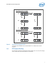
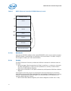
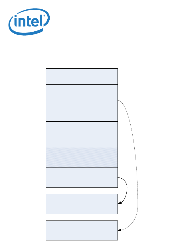
Table 5. 82575 Ethernet Controller EEPROM Memory Layout
3.2.3.1 EEUPDATE
Intel has an MS-DOS* software utility called EEUPDATE, which can be used to program
EEPROM images in development or production line environments. To obtain a copy of
this program, contact your Intel representative.
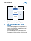
3.2.4 FLASH
The 82575 Ethernet Controller provides two different methods for software access to
the Flash.
• Using the legacy Flash transactions the Flash is read from, or written to, whenever
the host CPU performs a read or a write operation to a memory location that is
within the FLASH address mapping.
• Upon boot via accesses in the space indicated by the Expansion ROM Base Address
Register.
All accesses to the Flash require the appropriate command sequence for the device
used. Refer to the specific Flash data sheet for more details on reading from or writing
to Flash. Accesses to the Flash are based on a direct decode of CPU accesses to a
memory window defined in either:
1. 82575 Flash Base Address Register (PCIe Control Register at offset 14h or 18h).
HW Area
PXE Area
Reserved
FW pointers
FW structures
PCIE/PHY/PLL/SerDes structures
0
0X30
0x40
0x50
MAC address + SW Area
0xA