


45
82575 Ethernet Controller Design Guide
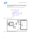
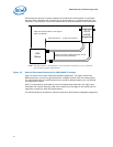
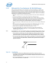
7.1.4.1 Signal Termination and Coupling
The four differential pairs of each port are terminated with 49.9 Ω (1% tolerance)
resistors, placed near the 82575 controller. One resistor connects to the MDI+ signal
trace and another resistor connects to the MDI- signal trace. The opposite ends of the
resistors connect together and to ground through a single 0.1μF capacitor. The
capacitor should be placed as close as possible to the 49.9 ohm resistors, using a wide
trace. Stubs created by the 49.9 Ω (1% tolerance) termination resistors should be kept
at a minimum.
Do not vary the suggested component values. Be sure to lay out symmetrical pads and
traces for these components such that the length and symmetry of the differential pairs
are not disturbed.
7.1.5 Signal Trace Geometry for 1000 BASE-T Designs
The key factors in controlling trace EMI radiation are the trace length and the ratio of
trace-width to trace-height above the reference plane. To minimize trace inductance,
high-speed signals and signal layers that are close to a reference or power plane should
be as short and wide as practical. Ideally, this trace width to height above the ground
plane ratio is between 1:1 and 3:1. To maintain trace impedance, the width of the trace
should be modified when changing from one board layer to another if the two layers are
not equidistant from the neighboring planes.
Each pair of signal should have a differential impedance of 100 Ω. +/- 15%. If a
particular tool cannot design differential traces, it is permissible to specify 55-65 Ω
single-ended traces as long as the spacing between the two traces is minimized. As an
example, consider a differential trace pair on Layer 1 that is 8 mils (0.2 mm) wide and
2 mils (0.05 mm) thick, with a spacing of 8 mils (0.2 mm). If the fiberglass layer is 8
mils (0.2mm) thick with a dielectric constant, E
R
, of 4.7, the calculated single-ended
impedance would be approximately 61 Ω and the calculated differential impedance
would be approximately 100 Ω.
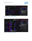
When performing a board layout, do not allow the CAD tool auto-router to route the
differential pairs without intervention. In most cases, the differential pairs will have to
be routed manually.
Note: Measuring trace impedance for layout designs targeting 100 Ω often results in lower
actual impedance. Designers should verify actual trace impedance and adjust the
layout accordingly. If the actual impedance is consistently low, a target of 105 – 110 Ω
should compensate for second order effects.
It is necessary to compensate for trace-to-trace edge coupling, which can lower the
differential impedance by up to 10 Ω, when the traces within a pair are closer than 30
mils (edge to edge).
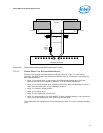
7.1.6 Trace Length and Symmetry for 1000 BASE-T Designs
As indicated earlier, the overall length of differential pairs should be less than four
inches measured from the Ethernet device to the magnetics.
The differential traces (within each pair) should be equal in total length to within 50
mils (1.25mm) and as symmetrical as possible. Asymmetrical and unequal length
traces in the differential pairs contribute to common mode noise. If a choice has to be
made between matching lengths and fixing symmetry, more emphasis should be placed
on fixing symmetry. Common mode noise can degrade the receive circuit’s performance
and contribute to radiated emissions.