


82575 Ethernet Controller Design Guide
48
7.1.14 Thermal Design Considerations
The 82575 Gigabit Ethernet Controller contains a thermal sensor that is accessible
through the SMBus. Trip points can be set in the EEPROM for the device.
IcePak* and FlowTherm* models are available for the 82575 Ethernet Controller;
contact your Intel representative for information.
Refer to the application note: Intel® 82575 Ethernet Controller Thermal Design
Considerations for more information.
7.2 Physical Layer Conformance Testing
Physical layer conformance testing (also known as IEEE testing) is a fundamental
capability for all companies with Ethernet LAN products. PHY testing is the final
determination that a layout has been performed successfully. If your company does not
have the resources and equipment to perform these tests, consider contracting the
tests to an outside facility.
7.2.1 Conformance Tests for 10/100/1000 Mbps Designs
Crucial tests are as follows, listed in priority order:
• Bit Error Rate (BER). Good indicator of real world network performance. Perform bit
error rate testing with long and short cables and many link partners. The test limit
is 10
-11
errors.
• Output Amplitude, Rise and Fall Time (10/100Mbps), Symmetry and Droop
(1000Mbps). For the 82575 controller, use the appropriate PHY test waveform.
• Return Loss. Indicator of proper impedance matching, measured through the RJ-45
connector back toward the magnetics module.
• Jitter Test (10/100Mbps) or Unfiltered Jitter Test (1000Mbps). Indicator of clock
recovery ability (master and slave for Gigabit controller).
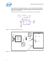
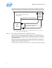
7.3 Troubleshooting Common Physical Layout Issues
The following is a list of common physical layer design and layout mistakes in LAN On
Motherboard Designs.
1. Lack of symmetry between the two traces within a differential pair. Asymmetry can
create common-mode noise and distort the waveforms. For each component and/or
via that one trace encounters, the other trace should encounter the same
component or a via at the same distance from the Ethernet silicon.
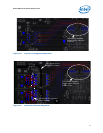
2. Unequal length of the two traces within a differential pair. Inequalities create
common-mode noise and will distort the transmit or receive waveforms.
3. Excessive distance between the Ethernet silicon and the magnetics. Long traces on
FR4 fiberglass epoxy substrate will attenuate the analog signals. In addition, any
impedance mismatch in the traces will be aggravated if they are longer than the
four inch guideline.
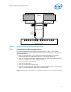
4. Routing any other trace parallel to and close to one of the differential traces.
Crosstalk getting onto the receive channel will cause degraded long cable BER.
Crosstalk getting onto the transmit channel can cause excessive EMI emissions and
can cause poor transmit BER on long cables. At a minimum, other signals should be
kept 0.3 inches from the differential traces.
5. Routing one pair of differential traces too close to another pair of differential traces.
After exiting the Ethernet silicon, the trace pairs should be kept 0.3 inches or more
away from the other trace pairs. The only possible exceptions are in the vicinities