19
82575 Ethernet Controller Design Guide
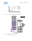
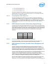
• 1.8 V must not exceed 3.3 V.
• 1.0 V must not exceed 3.3 V.
• 1.0 V must not exceed 1.8 V.
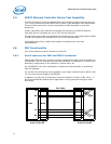
The power supplies are all expected to ramp during a short power-up internal
(approximately 20ms or better). Do not leave the device in a prolonged state were
some, but not all, voltages are applied.
3.4.1.1 Using Regulators With Enable Pins
The use of regulators with enable pins is very helpful in controlling sequencing.
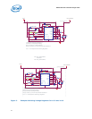
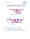
Connecting the enable of the 1.8 V regulator to 3.3 Vwill allow the 1.8 V to ramp as
shown in Figure 3. Connecting the enable of the 1.0 V regulator to the 1.8 V output
assures that the 1.0 V rail will ramp after the 1.8 V rail. This provides a quick solution
to power sequencing. Make sure to check design parameters for inputs with this
configuration.
3.4.2 82575 Ethernet Controller Device Power Supply Filtering
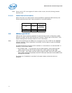
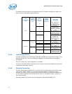
Provide several high-frequency bypass capacitors for each power rail (see table below),
selecting values in the range of 0.01µF to 0.1µF. If possible, orient the capacitors close
to the device and adjacent to power pads. Decoupling capacitors should connect to the
power planes with short, thick (18 mils or more) traces and 14 mil vias. Long and thin
traces are more inductive and would reduce the intended effect of decoupling
capacitors.
Table 6. Minimum Number of Bypass Capacitors per Power Rail.
Furnish approximately 4.7µF to 10µF of bulk capacitance for all the power rails;
placement should be as close to the device power connection as possible.
3.4.3 82575 Ethernet Controller Controller Power Management and
Wake Up
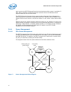
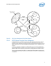
The 82575 Ethernet Controller Gigabit Ethernet Controller supports low power
operation as defined in the PCI Bus Power Management Specification. There are two
defined power states, D0 and D3. The D0 state provides full power operation and is
divided into two sub-states: D0u (uninitialized) and D0a (active). The D3 state provides
low power operation and is also divided into two sub-states: D3hot and D3cold.
To enter the low power state (D3), the software driver must stop data transmission and
reception. Either the operating system or the driver must program the Power
Management Control/Status Register (PMCSR) and the Wakeup Control Register
(WUC). If wakeup is desired, the appropriate wakeup LAN address filters must also be
set. The initial power management settings are specified by EEPROM bits.
When the 82575 Ethernet Controller transitions to either of the D3 low power states,
the 1.0 V, 1.8 V, and 3.3 V sources must continue to be supplied to the device.
Otherwise, it will not be possible to use a wakeup mechanism. The AUX_PWR signal is a
Power Rail
4.7uF or
10uF
0.1uF
3.3 V 1 2
1.8 V 1 4
1.0 V 1 6


