


21
82575 Ethernet Controller Design Guide
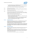
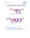
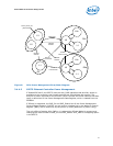
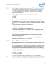
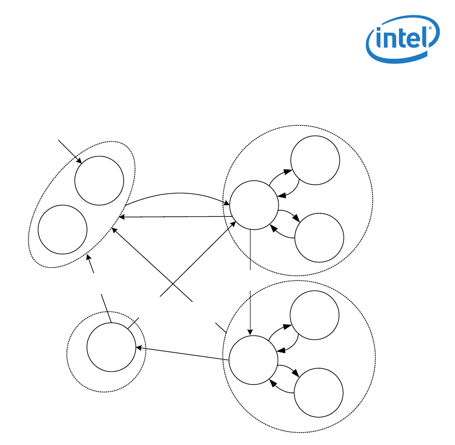
Figure 8. PCIe Power Management Flow/State Diagram
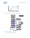
3.4.4.2 82575 Ethernet Controller Power Management
If DisableD3Cold=0, the 82575 uses the AUX_PWR indication that auxiliary power is
available to the controller, and therefore advertises D3cold Wake Up support. The
amount of power required for the function (which includes the entire network interface
card) is advertised in the Power Management Data Register, which is loaded from the
EEPROM.
If D3cold is supported, the PME_En and PME_Status bits of the Power Management
Control/Status Register (PMCSR), as well as their shadow bits in the Wake Up Control
Register (WUC) will be reset only by the power up reset (detection of power rising).
The only effect of setting AUX_PWR to 1 is advertising D3cold Wake Up support and
changing the reset function of PME_En and PME_Status. AUX_PWR is a strapping option
in the 82575.
L3
L1
PERST# de-
assertion
PERST#
assertion
PERST#
assertion
PERST#
assertion
Write 11
to Power State
Write 00
to Power State
Enable
master Access
Internal_Power_On
_Reset assertion
L2
L0
L0s
L1
Dr
D0u
L0
L0s
L1
D0a
D3