


82575 Ethernet Controller Design Guide
44
7.1.4 Differential Pair Trace Routing for 10/100/1000 Designs
Trace routing considerations are important to minimize the effects of crosstalk and
propagation delays on sections of the board where high-speed signals exist. Signal
traces should be kept as short as possible to decrease interference from other signals,
including those propagated through power and ground planes. Observe the following
suggestions to help optimize board performance:
• Maintain constant symmetry and spacing between the traces within a differential
pair.
• Minimize the difference in signal trace lengths of a differential pair.
• Keep the total length of each differential pair under 4 inches. Although possible,
designs with differential traces longer than 5 inches are much more likely to have
degraded receive BER (Bit Error Rate) performance, IEEE PHY conformance
failures, and/or excessive EMI (Electromagnetic Interference) radiation.
• Do not route a pair of differential traces closer than 100 mils to another differential
pair.
• Do not route any other signal traces parallel to the differential traces, and closer
than 100 mils to the differential traces (300 mils is recommended).
• Keep maximum separation within differential pairs to 7 mils.
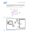
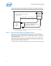
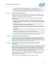
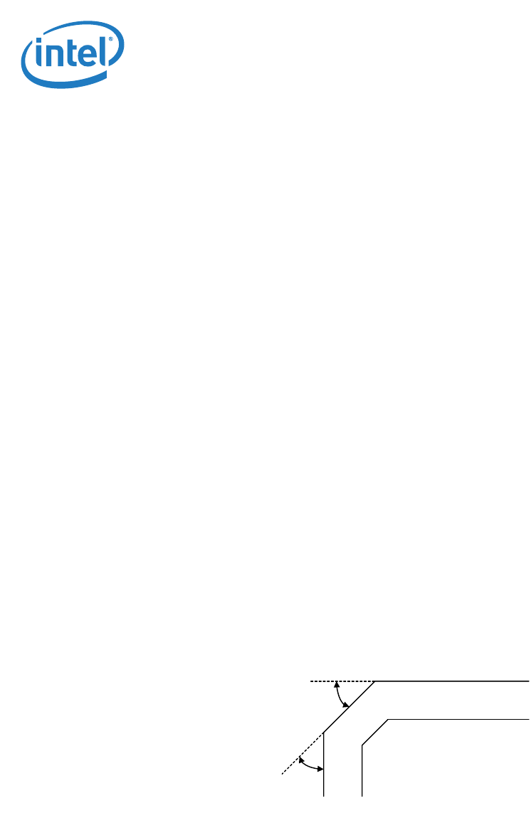
• For high-speed signals, the number of corners and vias should be kept to a
minimum. If a 90° bend is required, it is recommended to use two 45° bends
instead. Refer to Figure 16.
Note: In manufacturing, vias are required for testing and troubleshooting purposes. The via
size should be a 17-mil (±2 mils for manufacturing variance) finished hole size (FHS).
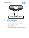
• Traces should be routed away from board edges by a distance greater than the
trace height above the reference plane. This allows the field around the trace to
couple more easily to the ground plane rather than to adjacent wires or boards.
• Do not route traces and vias under crystals or oscillators. This will prevent coupling
to or from the clock. And as a general rule, place traces from clocks and drives at a
minimum distance from apertures by a distance that is greater than the largest
aperture dimension
.
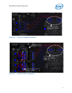
Figure 16. Trace Routing
• The reference plane for the differential pairs should be continuous and low
impedance. It is recommended that the reference plane be either ground or 1.8 V
(the voltage used by the PHY). This provides an adequate return path for and high
frequency noise currents.
• Do not route differential pairs over splits in the associated reference plane as it
may cause discontinuity in impedances.
45°
45°